Chemiresistor for use in conducting electrolyte solution

a chemiresistor and conducting electrolyte technology, applied in the field of chemical sensors, can solve the problems of not teaching the use of conducting nanoparticle based chemiresistors, desensitizing the performance of sensors, etc., and not being suitable for liquid phase detection

Active Publication Date: 2010-11-04
COMMONWEALTH SCI & IND RES ORG
View PDF17 Cites 22 Cited by
  • Summary
  • Abstract
  • Description
  • Claims
  • Application Information

AI Technical Summary

Benefits of technology

[0008]The present inventors have now determined that by controlling the ratio of the chemiresistor film impedance to the impedance due to the double layer capacitance of the total electrode surface in contact with the electrolyte so

Problems solved by technology

However, the above disclosures do not teach how to use conducting nanoparticle based chemiresistors in an ionically conductive liquid phase in particular in an ionically conductive aqueous liquid phase (i.e. an electrolyte solution).
This bypass resistor typically desensitizes the performance of the sensor”.
Vossmeyer also teaches that the simple chemiresi

Method used


Image

  • Chemiresistor for use in conducting electrolyte solution
  • Chemiresistor for use in conducting electrolyte solution
  • Chemiresistor for use in conducting electrolyte solution

Examples


example 1

Synthesis of DMAP-Au gold nanoparticles

[0097]Gold nanoparticles were synthesised following the Brust method (Brust, M. et al. J. Chem. Soc. Chem. Commun 1994, 801-802) and transferred to the aqueous phase following the method by Gittins (Gittins, D. I.; Caruso, F. Angew. Chemie Int. Ed. 2001, 40, 3001-3004). Briefly, a solution of HAuCl4 was added to a stirred solution of tetraoctylammonium bromide (TOAB) in toluene. Stirring was continued for 10 min and was followed by the addition of sodium borohydride which resulted in reduction of the gold. After 2 hours, the lower aqueous phase was removed and the toluene phase was subsequently washed twice with sulfuric acid, twice with sodium carbonate and twice with water. For the spontaneous and complete phase transfer of the nanoparticles from the organic to the aqueous phase, an aqueous solution of dimethylamino pyridine (DMAP) was added to the as-prepared nanoparticles. The solution containing the DMAP coated gold nanoparticles (DMAP-Au)...

example 2

Preparation of Band Microelectrodes

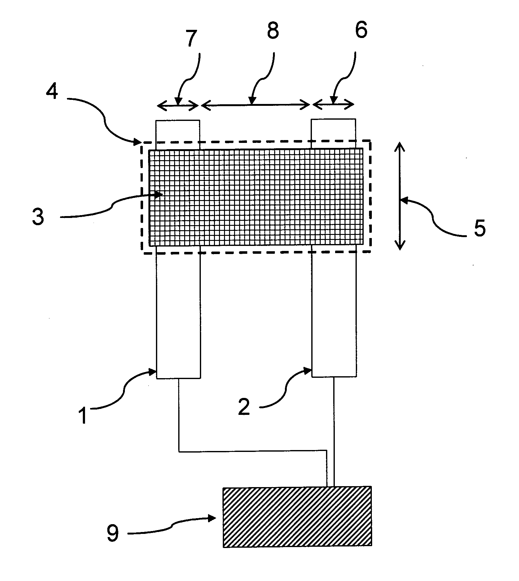
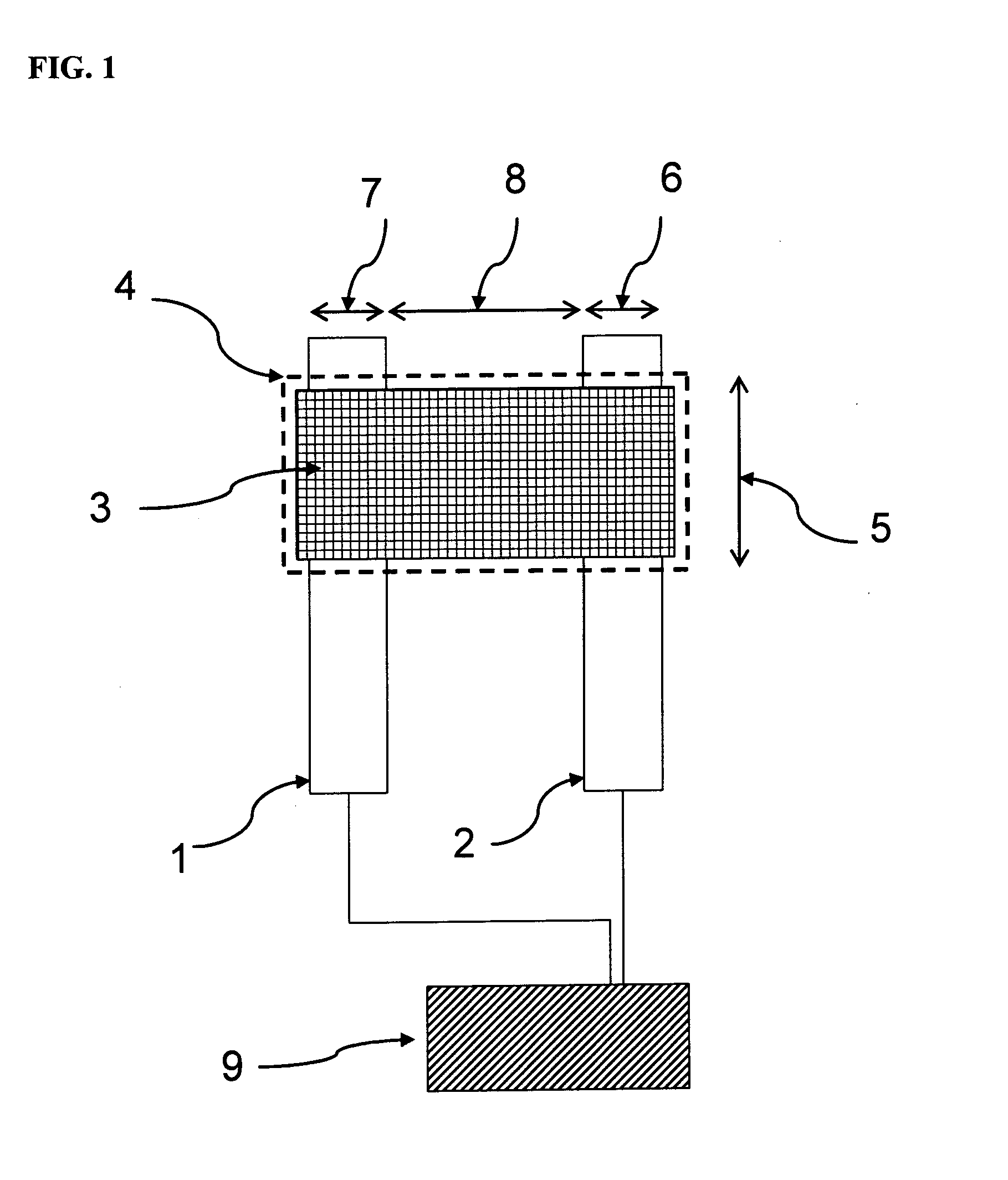
[0098]Glass microscope slides were cleaned and coated by vacuum evaporation with an adhesion layer of chromium, followed by a layer of gold. Standard photolithography techniques and etching techniques were used to produce a band microelectrode as shown in FIG. 1 consisting of two parallel gold electrodes that were 3 mm long, 5 microns wide and separated by a 5 micron gap between the two gold electrodes. An array of six such band microelectrodes were produced on each glass slide.

[0099]The glass slides patterned with the six gold band microelectrodes were pre-treated with a silylating agent (mercaptopropyl triethoxysilane, MPTES) prior to gold nanoparticle deposition for better adhesion of the nanoparticle to the glass and the electrode surface. Thus, the glass slides were immersed in a solution containing 2% v / v MPTES in toluene for two hours, followed by rinsing with copious amounts of toluene and drying under a gentle stream of nitrogen. The treat...

example 3

Formation of Chemiresistor Sensors Using Inkjet Printing Using a 1% w / v DMAP-Au Solution

[0100]Inkjet printing of DMAP-Au solution was carried using an Autodrop printing system (from Microdrop Technologies, Germany). The printhead used was an AD-K-501 micropipette (25 μL holding volume, 70 μm diameter nozzle). The micropipette was filled with a 1% w / v DMAP-Au aqueous solution that had been placed in a 96-well plate positioned on the printing platform. A rectangular voltage pulse was applied to dispense droplets from the micropipette nozzle with a typical droplet volume of 180 pL. The drop frequency was set at 200 Hz and the tip of the micropipette was positioned 1 mm above the substrate during the printing process. The band microelectrodes were prepared as per example 2 and were positioned on the inkjet printer platform in a suitable position.

[0101]Subsequently, 10 drops of a 1% w / v DMAP-Au aqueous solution were then inkjet-printed over each of the six band microelectrodes on the gla...


PUM

PropertyMeasurementUnit
Electrical conductivityaaaaaaaaaa
Concentrationaaaaaaaaaa
Lengthaaaaaaaaaa

Abstract

The present invention provides a chemiresistor-based sensor for measuring the presence or amount of analyte in an electrolyte solution; said chemiresistor comprising (i) a chemiresistor film wherein the impedance of said nanoparticle film changes in the presence of an analyte; and (ii) two electrically conducting electrodes in electrical contact with said nanoparticle film; wherein said electrically conducting electrodes are adapted to be connected to a device for measuring the impedance of said chemiresistor film under a voltage signal and wherein the impedance of the double layer capacitor formed by the two electrically conducting electrodes in the presence of the electrolyte solution, is larger than the impedance of the chemiresistor film either before or after exposure of the chemiresistor film to the analyte. A method of using said chemiresistor-based sensor to measure the presence or amount of analyte is also provided. Further provided is a method of determining the partition coefficient of an analyte using said chemiresistor-based sensor.

Description

FIELD OF THE INVENTION[0001]The present invention relates to chemical sensors, in particular to chemiresistors that are capable of detecting analytes in a liquid environment that potentially has a high ionic conductivity.BACKGROUND OF THE INVENTION[0002]Chemiresistors are a class of chemical sensors wherein the electrical resistance of a sensing element changes in response to the presence or absence of a chemical species. Chemiresistors are attractive for use as chemical sensors as it is relatively easy to measure and record small changes in electrical resistance.[0003]Chemiresistors and arrays of chemiresistors for determining the level of analytes in the vapour or gas phase are well established in the art. One method of realising such a chemiresistor is to mix a conducting material such as carbon black with a conducting or non-conducting polymer (Lonergan et al., Chem Mater., 1996, 8, 2298; Doleman et al, Anal. Chem., 1998, 70, 4177; Sotzing et al, Chem Mater., 2000, 12, 593). Thi...

Claims


Application Information

Patent Timeline
IPC IPC(8): G01N27/26B05D5/12
CPCG01N27/127Y10T436/11G01N27/26
Inventor RAGUSE, BURKHARDCHOW, EDITH
Owner COMMONWEALTH SCI & IND RES ORG
Why Eureka
Try Eureka