Absorptive heat pump systems and heating method

a heat pump and circulation technology, applied in the field of absorption heat pump circulation technology in thermal engineering, can solve the problems of limited application of the heat pump circulation system in the area without high-grade heat source and water source, difficult to utilize in the high-energy consumption industry, and limit the improvement of the heat pump circulation heating coefficient. , to achieve the effect of improving the heating coefficient, and improving the efficiency of the heat pump circulation system

Inactive Publication Date: 2010-11-11
BEIJING LIANLI ENERGY TECH CO LTD
View PDF14 Cites 21 Cited by
  • Summary
  • Abstract
  • Description
  • Claims
  • Application Information

AI Technical Summary

Benefits of technology

[0005]It is the fundamental object of the present invention to overcome the existing problem of the absorptive heat pump circulation system and the heating method, and provide an absorptive heat pump circulation system of self-energized driving heat source and a heating method, and the technical problem to be solved is to operate absorptive heating under the condition of only one external driving heat source, to output heat energy with high grade outward, in order to significantly improve heating coefficient, i.e. energy efficiency, so that it has more practicability and more industry value.
[0030]compressing the refrigeration working medium, to increase the pressure and temperature of the refrigeration working medium;
[0035]Compared with current technology, the present invention possesses obvious advantage and beneficial effects. According to the above technical solution, because of an absorbent crystallizer and the heating energy generated by the absorber being provided to the generator directly through the heat cycling loop, the absorptive heat pump circulation systems and heating method of the present invention therefore can basically omit the external driving heat source required by the generator in the current absorptive heating circulation system to realize absorptive heating, so that the coefficient of performance (COP) is improved and the temperature of the driving heat source required, i.e. the temperature of the available excess heat at a low temperature, is significantly decreased, so as to be more practical.
[0036]Besides, since the absorptive heat pump system of the present invention needs no setting of a condenser, therefore, different from the current absorption heat pump circulation, the present invention does not adopt condensation water to cool down the condenser, so that the operational load of the cooling tower can be largely reduced, meanwhile the water resource is saved.

Problems solved by technology

That is to say, the current heat pump circulation system must utilize two external driving heat sources in the generator and the evaporator concurrently, which not only limits the improvement of the heat pump circulation heating coefficient, but also limits the application of the heat pump circulation system in the area in lack of high grade heat source and water source.
The driving heat source in the technical solution described above can utilize the excess heat at a low temperature of great volume and difficult to utilize in the high-energy consumption industry, such as steel industry, building material industry and chemistry industry.

Method used


Image

  • Absorptive heat pump systems and heating method
  • Absorptive heat pump systems and heating method
  • Absorptive heat pump systems and heating method

Examples


embodiment 1

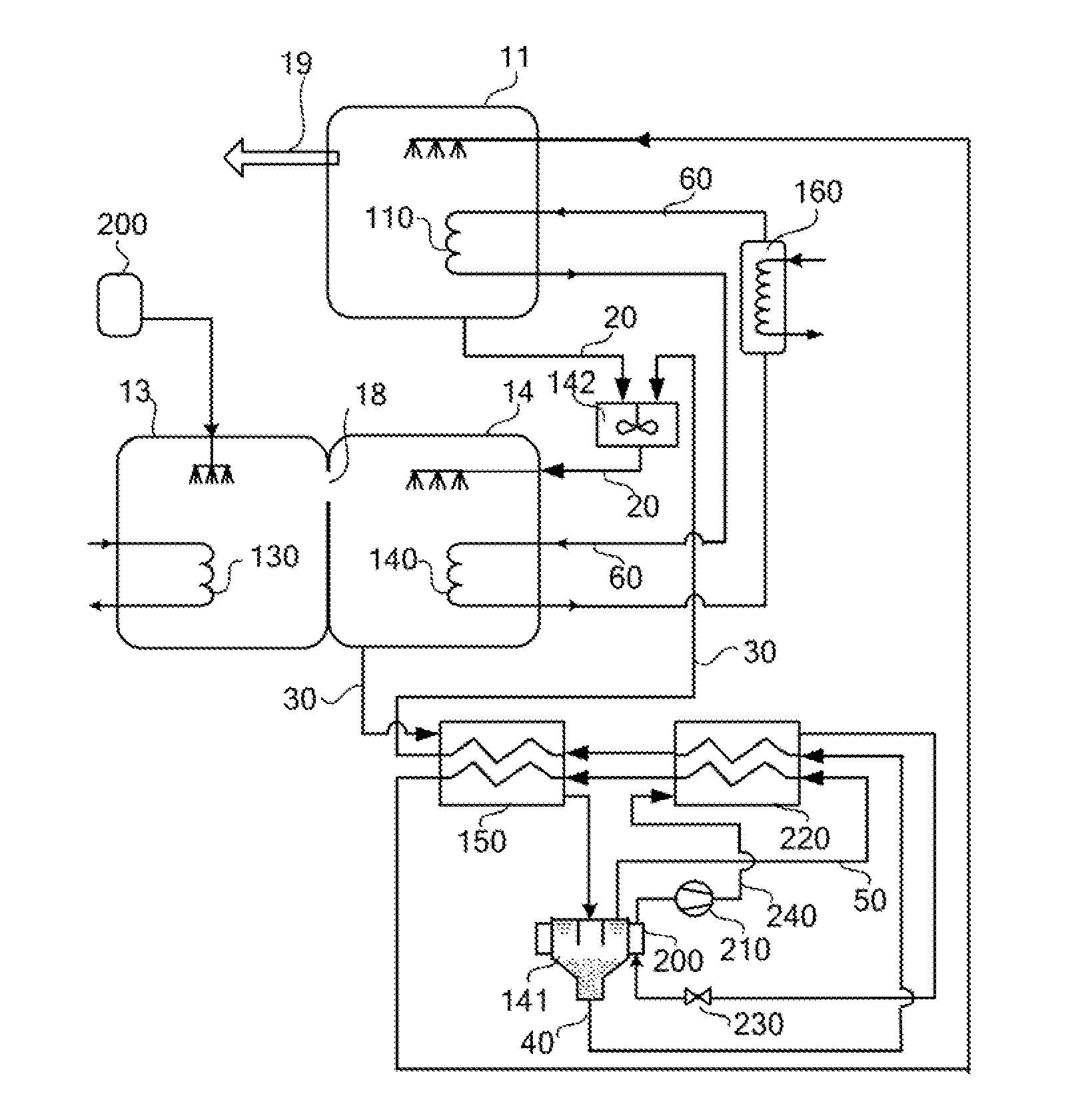
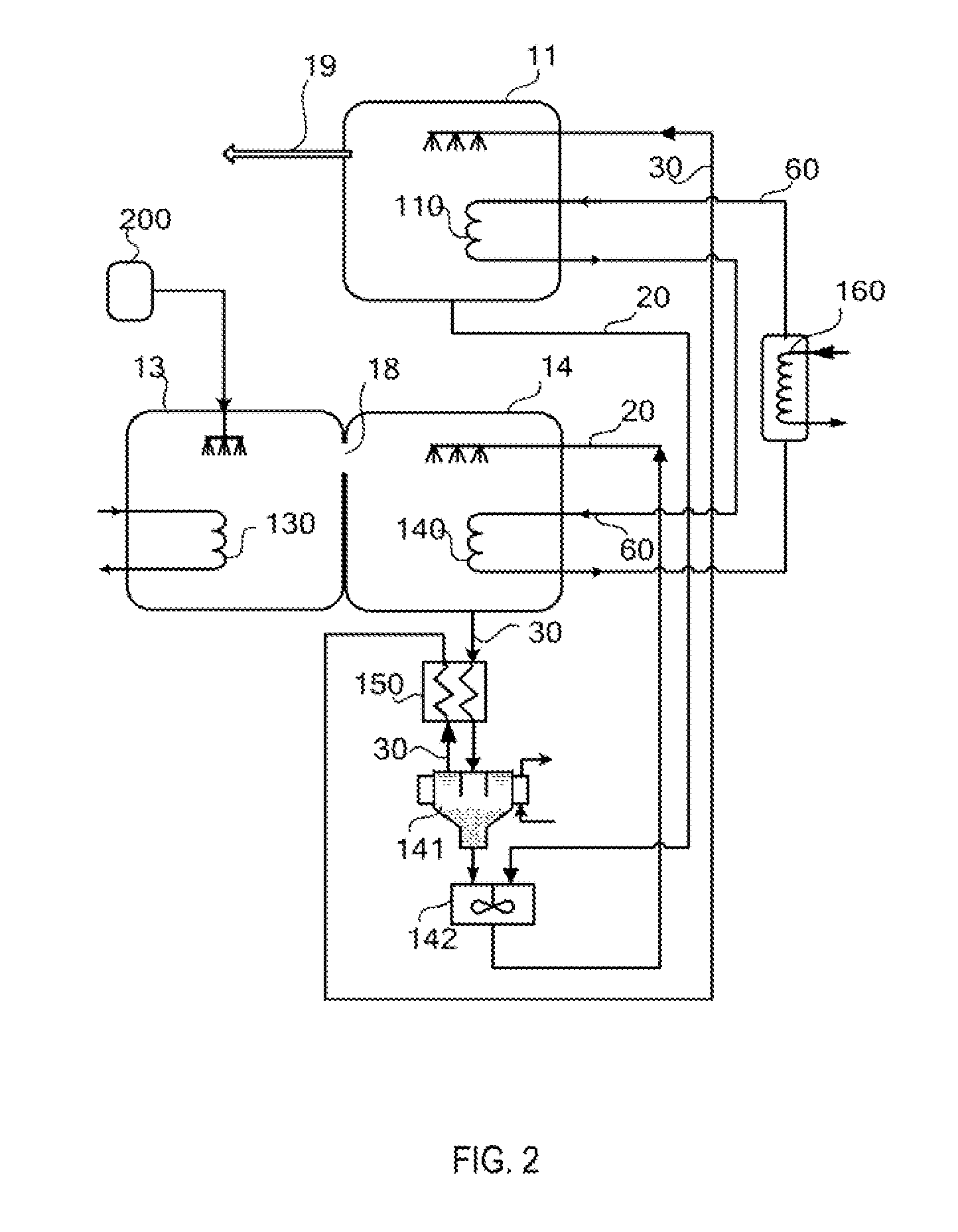
[0091]Employing the method of the sixth embodiment described, the present embodiment utilizes hot water of 100° C. as the driving heat source of the evaporator, and applies saturated steam of 195° C. as the external heat source to heat the working medium in the thermal cycling loop, so as to compensate the thermal deficiency part of the heating capacity for the driving heat source of the generator caused by dissipation loss, utilizes dimethyl silicon oil as thermal cycling working medium, and utilizes cooling water of 20° C. to cool the absorbent crystallizer 141. In the present embodiment, the temperature outputted outward is 182° C., the pressure of the superheated vapor is 170 kPa, and coefficient of performance (COP) is 10.0. The COP of the present embodiment is calculated according to the following function:

COP=—heating capacity outputted / heat capacity of external heating source employed

embodiment 2

[0092]Employing the method of the sixth embodiment described, the present embodiment utilizes hot water of 100° C. as the driving heat source of the evaporator, and applies saturated steam of 195° C. as the external heat source to heat the working medium in the thermal cycling loop, so as to compensate the thermal deficiency part of the heating capacity for the driving heat source of the generator caused by dissipation loss, utilizes dimethyl silicon oil as thermal cycling working medium, and utilizes cooling water of 60° C. to cool the absorbent crystallizer 141. In the present embodiment, the temperature outputted outward is 182° C., the pressure of the superheated vapor is 170 kPa, and coefficient of performance (COP) is 10.0. The COP of the present embodiment is calculated according to the following function:

COP=heating capacity outputted / heat capacity of external heating resource employed

embodiment 3

[0093]Employing the method of the seventh embodiment described, the present embodiment utilizes hot water of 80° C. as the driving heat source of the evaporator, and applies saturated steam of 160° C. as the external heat source to heat the working medium in the thermal cycling loop, so as to compensate the thermal deficiency part of the heating capacity for the driving heat source of the generator caused by dissipation loss, applies dimethyl silicon oil as thermal cycling working medium, and utilizes cooling water of −18° C. to cool absorbent crystallizer 141. In the present embodiment, the temperature outputted outward is 148° C., the pressure of the superheated vapor is 95 kPa, and coefficient of performance (COP) is 5.5. The COP of the present embodiment is calculated according to the following function:

COP=heating capacity outputted / (heat capacity of external heating source employed+power consumption of compressor*3.0)

[0094]Wherein, the primary energy generating efficiency of t...


PUM


Abstract

The present invention relates to an absorptive heat pump circulation systems and heating method. According to the present invention, an absorption heat pump circulation system comprises: a generator, equipped with a heat exchanger; an evaporator, equipped with a driving heat source; an absorber, equipped with a heat exchanger; and an absorbent crystallizer. An absorption solution entrance of the crystallizer is connected to an absorption solution exit of the absorber and a crystallized absorption solution exit of the crystallizer is connected to an absorption solution entrance of the generator, and a crystal output of the crystallizer is connected to an absorption solution Entrance of the absorber; The heat exchanger of the generator and the heat exchanger of the absorber are connected to form a thermal cycling loop, which transfers the absorption heat generated by the absorber to the generator. Since the absorbent crystallizer is provided, and the heat generated by the absorber is provided to the generator directly through the thermal cycling loop, then the external driving heat source required by the generator in the traditional absorption heating circulation system is essentially saved, so that the coefficient of performance is significantly improved. The present invention extensively applies to the utilization of excess heat at a low temperature as well as energy-saving and emission-reducing in the fields such as chemical industry, food industry, sewage treatment, sea water desalination and so on.

Description

FIELD OF THE INVENTION[0001]The present invention in general relates to absorptive heat pump circulation technology in thermal engineering field, in particular, relates to absorptive heat pump system and heating method that carry absorptive heating under the condition of only one set of external driving heat source and output heat of high grade outward, which extensively apply to the utilization of excess heat at a low temperature and also energy-saving and emission-reducing in the process of distillation fractionation, evaporation concentration, materials desiccation, adsorbent regeneration and so on, in the fields of such as chemical industry, food industry, sewage treatment, sea water desalination and so on.BACKGROUND OF THE INVENTION[0002]With reference to FIG. 1, current absorptive heat pump circulation system is characterized in utilizing absorption solution can precipitate steam with components of low boiling points under a certain condition, and can intensively absorb steam ...

Claims


Application Information

Patent Timeline
Patent Type & Authority Applications(United States)
IPC IPC(8): F25B29/00F25B17/00F25B1/00F25B41/00
CPCF25B15/02Y02B30/62F25B29/006F25B15/06Y02A30/27Y02P20/10
Inventor SU, QINGQUAN
Owner BEIJING LIANLI ENERGY TECH CO LTD
Why Eureka
Try Eureka