Heat spreader structure and method of manufacturing the same

a heat spreader and heat pipe technology, applied in the direction of lighting and heating apparatus, semiconductor/solid-state device details, applications, etc., can solve the problems of heat pipe burnout, adversely affecting the operation efficiency of electronic devices, and the work performance of heat pipes, etc., to achieve excellent heat spreading performance, good bonding power, and high thermal conductivity

Inactive Publication Date: 2010-12-23
CHEN WEI EN +1
View PDF5 Cites 10 Cited by
  • Summary
  • Abstract
  • Description
  • Claims
  • Application Information

AI Technical Summary

Benefits of technology

[0015]To achieve the above and other objects, the method of manufacturing the heat spreader structure according to a further embodiment of the present invention includes the following steps: providing at least one metal-made body, at least one metal-mesh layer, and a plurality of carbonaceous particles; evenly distributing the carbonaceous particles on the metal-made body at predetermined deposition areas; using the metal-mesh layer to cover and thereby hold the evenly distributed carbonaceous particles in place to form a carbonaceous matter-metal composite layer; and causing the carbonaceous matter-metal composite layer to bond to the metal-made body through sintering. According to a still further embodiment of the present invention; the above-described method can further include a step before the evenly distributing step to coat at least one layer of metal coating on outer faces of the carbonaceous particles; and a step before the coating step to form a carbonized layer on the outer faces of the carbonaceous particles. The carbonized layer can be formed using a material selected from the group consisting of chromium (Cr), titanium (Ti), tungsten (W) molybdenum (Mo), silicon (Si), and vanadium (V); the material for forming the metal coating can be selected from the group consisting of copper (Cu), aluminum (Al), and silver (Ag); and the carbonaceous particles can be selected from the group consi

Problems solved by technology

The heat produced by the electronic elements during the operation thereof must be timely removed, lest the heat should adversely affect the operation efficiency of the electronic devices to even cause burnout of the electronic elements thereof.
However, the work performance of the heat pipe is subject to two factors, that is, capillary pressure difference and backflow resistance.
However, the small capillary porosity will also increase the frictional force to cause frictional flow of the working fluid when flowing back to the vaporizing end.
The large backflow resistance to the working fluid will result in slow backflow speed of the working fluid and dry burning of the heat pipe at the vaporizing end.
On the other hand, when the capillary porosity is large, the working fluid is subject to relatively low backflow resistance, and capillary pressure difference for sucking the condensed liquid into the capillary structure is small, too.
Since the capillary structure in the heat pipe is formed by bonding copper powder to the inner wall surface of the heat pipe through sintering in powder metallurgy, and the sintered capillary structure contains pores, the bonding strength between the copper powder and the inner wall surface of the heat pipe is low, and the copper powder tends t

Method used


Image

  • Heat spreader structure and method of manufacturing the same
  • Heat spreader structure and method of manufacturing the same
  • Heat spreader structure and method of manufacturing the same

Examples


first embodiment

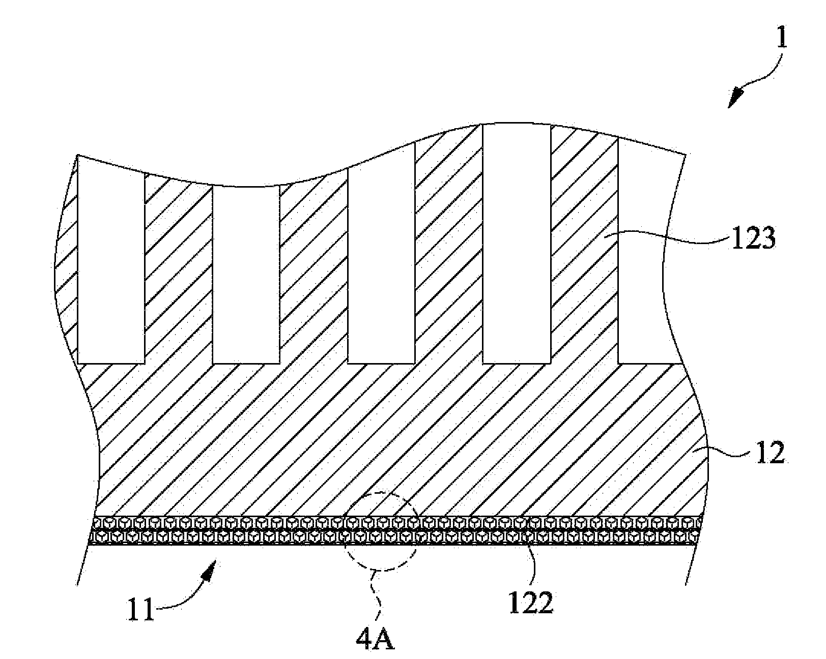
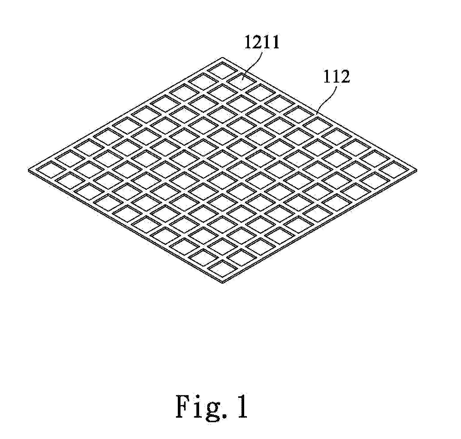
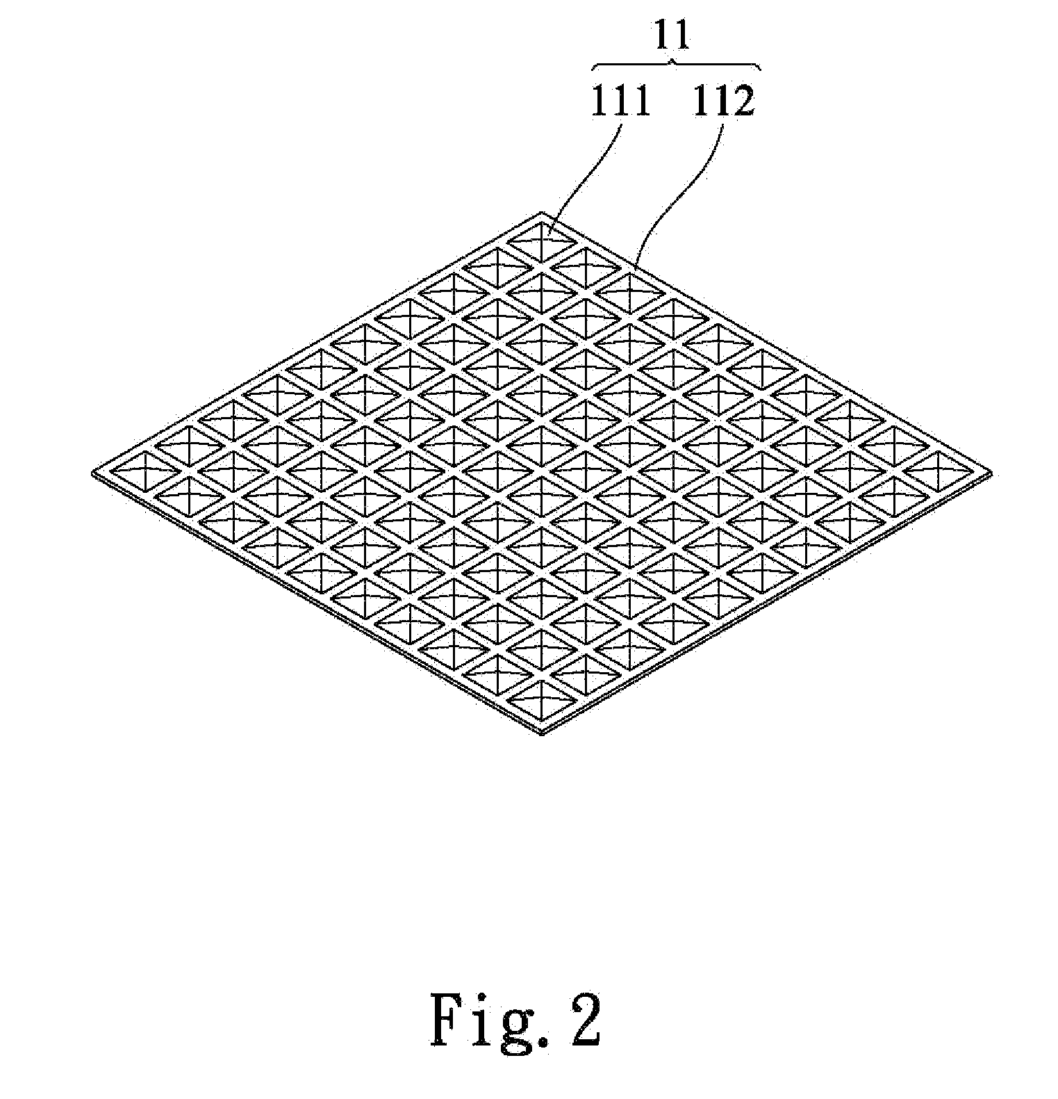
[0054]Please refer to FIGS. 1, 2, 3A-B, 4, 4A, 5, and 5A-C. A heat spreader structure 1 according to the present invention includes at least one carbonaceous matter-metal composite layer 11 including a plurality of carbonaceous particles 111 and at least one metal-mesh layer 112. The metal-mesh layer 112 has a plurality of meshes 1121, and can be made of a material selected from the group consisting of copper (Cu), aluminum (Al), silver (Ag), and Nickel (Ni). In a first form of the carbonaceous matter-metal composite layer 11, the carbonaceous particles 111 are separately firmly held inside the meshes 1121 of the metal-mesh layer 112, as shown in FIG. 3B. In a second form of the carbonaceous matter-metal composite layer 11, the carbonaceous particles 111 are covered and held in place by the metal-mesh layer 112, as shown in FIG. 3A. The carbonaceous particles 111 are selected from the group consisting of diamond and graphite particles. In a first example of application, the carbonac...

second embodiment

[0068]FIG. 17 is a sectional view of the heat spreader structure 1 manufactured according to the method according to the present invention.

[0069]FIG. 15 is a flowchart showing the steps included in a method according to a third embodiment of the present invention for manufacturing the heat spreader structure as shown in FIGS. 1, 2, 3A, 4, 4A, 5 and 5A-C. The steps included in the method of the third embodiment are:

[0070]Step 51: providing at least one metal-made body at least one metal-mesh layer and a plurality of carbonaceous particles. In the step 51, at least one metal-made body 12, at least one metal-mesh layer 112, and a plurality of carbonaceous particles 111 are provided. The metal-made body 12 can be configured as any one of a heat sink as shown in FIG. 4, a heat pipe as shown in FIG. 5, and a flat heat pipe as shown in FIG. 5B. The carbonaceous particles 111 can have a particle size ranged from 1 μm to 2 mm, and preferably ranged from 100 μm to 150 μm. The metal-mesh layer...

fourth embodiment

[0075]FIG. 18 is a sectional view of the heat spreader structure 1 manufactured according to the method according to the present invention.

[0076]In the methods according to the present invention for forming the heat spreader structure 1, the material for forming the carbonized layer 1112 can be selected from the group consisting of chromium (Cr), titanium (Ti), tungsten (W), molybdenum (Mo), silicon (Si), and vanadium (V); the material for the metal coating 1111 can be selected from the group consisting of copper (Cu), aluminum (Al), and silver (Ag); the carbonaceous particles 111 can be selected from the group consisting of diamond particles and graphite particles; and the metal particles 113 can be selected from the group consisting of copper (Cu), aluminum (Al), silver (Ag), and nickel (Ni) particles, and are preferably copper particles.


PUM

PropertyMeasurementUnit
Efficiencyaaaaaaaaaa
Thermal conductivityaaaaaaaaaa

Abstract

A heat spreader structure includes at least one carbonaceous matter-metal composite layer having a plurality of carbonaceous particles and at least one metal-mesh layer having a plurality of meshes. The carbonaceous particles are either separately firmly held inside the meshes of the metal-mesh layer or covered and held in place by the metal-mesh layer. The carbonaceous matter-metal composite layer can be coated on a metal-made body through sintering to ensure good bonding of the carbonaceous particles to the metal-made body and accordingly enhance the heat spreading efficiency of the metal-made body. A method for manufacturing the heat spreader structure is also disclosed.

Description

FIELD OF THE INVENTION[0001]The present invention relates to a heat spreader structure, and more particularly, to a heat spreader structure providing excellent heat spreader performance; and the present invention also relates to a method of manufacturing the heat spreader structure.BACKGROUND OF THE INVENTION[0002]The heat produced by electronic elements in various electronic devices increases with the increasing computing speed and data processing capability of the electronic devices. The heat produced by the electronic elements during the operation thereof must be timely removed, lest the heat should adversely affect the operation efficiency of the electronic devices to even cause burnout of the electronic elements thereof. According to a conventional way of removing such heat, a cooling unit is provided on a top of an electronic element. In most cases, the conventional cooling unit is a radiation fin assembly or a heat sink. In some cases, the conventional cooling unit further in...

Claims


Application Information

Patent Timeline
IPC IPC(8): F28F21/02B05D3/02B05D7/00C04B37/02F28F21/08B21D53/02
CPCF28D15/046H01L23/373F28F2013/006Y10T29/4935H01L2924/0002H01L2924/00
Inventor CHEN, WEI-ENCHEN, YING-TUNG
Owner CHEN WEI EN
Why Eureka
Try Eureka