Coated Fibers for Culturing Cells

a technology of coated fibers and cells, applied in the field of cell culture, can solve the problems of microcarriers having difficulties in their use, difficult separation from the medium, excessive curvature, etc., and achieve the effects of improving coating uniformity, coating thickness control, and low cos

Inactive Publication Date: 2011-02-03
CORNING INC
View PDF5 Cites 5 Cited by
  • Summary
  • Abstract
  • Description
  • Claims
  • Application Information

AI Technical Summary

Benefits of technology

[0008]One or more of the various embodiments presented herein provide one or more advantages over prior articles and systems for culturing cells. For example, synthetic coated fibers described herein have been shown to support cell adhesion without the need of animal derived biocoating which limits the risk of pathogen contamination. This is especially relevant when cells are dedicated to cell-therapies. Further, large scale culture of cells is possible with coated fibers as described herein. Such coated fibers may also be advantageously used for culturing cells when animal derived products such as collagen, gelatin, fibronectin, etc. are undesired or prohibited. The methods described herein allow for the preparation of coated fibers having a wide range of properties such as stiffness, swellability, and surface chemistries. Further, in various embodiments, processes associated with the production of optical fibers may be employed to allow for low cost fabrication compared to other microcarriers available in the market. For example, it may be possible to produce many kilometers of coated fiber very short timeframe. Further such methods may provide for improved coating uniformity and coating thickness control as compared to the use of other coating processes (solution coating, dip coating etc). Using a fiber draw process, variables such as coating modulus, coating thickness, and overall fiber diameter (adjust surface area) can easily be changed in a low cost manner. Such coated fibers can provide for ease of handling when changing cell culture media (as compared to using small low density beads), and may allow for simplified harvesting of cells by running fibers through a stripper similar to that used to remove the coatings from an optical fiber. These and other advantages will be readily understood from the following detailed descriptions when read in conjunction with the accompanying drawings.

Problems solved by technology

However, microcarriers do have difficulties associated with their use.
Because of the low density required to keep them suspended in the culture medium, they can be difficult to separate from the medium when it is time to remove them from the assay.
Also, in order to increase surface area, the size of the bead must be decreased which leads to excessive curvature, which may not be suitable for many anchorage dependent cells.

Method used


Image

  • Coated Fibers for Culturing Cells
  • Coated Fibers for Culturing Cells
  • Coated Fibers for Culturing Cells

Examples


example 1

Coating of Optical Fiber

[0092]A variety of coatings suitable for cell culture were applied to the exterior surfaces of optical fibers. Briefly, the fibers with an outer diameter of 245 micrometers were coated with a compositions having components are indicated in Table 2, where Irgacure 819 is Bis(2,4,6-trimethylbenzoyl)-phenylphosphineoxide, and Irgacure 184 is 1-Hydroxycyclohexyl phenylketone.

TABLE 2Coating CompositionsWeight PercentComponentExample 1Example 2Example 32-Hydroxyethyl776020methacrylate2-Carboxyethyl202020acrylateTriethyleneglycol32060diacrylateIrgacure 8191.5 pph1.5 pph1.5 pphIrgacure 1841.5 pph1.5 pph1.5 pph

[0093]To produce the coating compositions in Table 2, the appropriate amount of each monomer and initiator was weighed into a jacketed beaker and heated to 70° C. followed by mixing until the photoinitiators were completely dissolved.

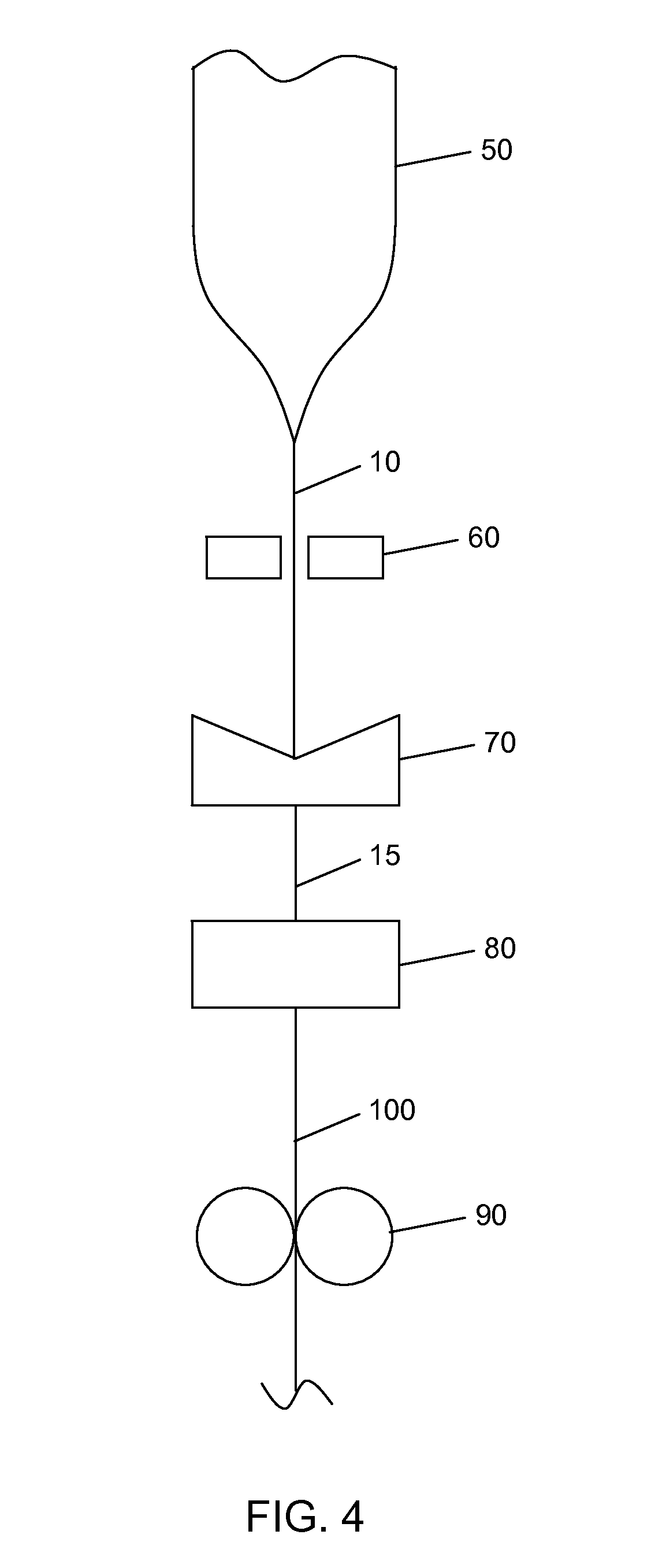
[0094]The coatings were applied to an optical fiber using an optical fiber draw. Using compositions prepared as described in Table...

example 2

Crystal Violet Staining to Verify Fiber was Coated

[0095]Crystal violet staining was used to verify that the fibers of EXAMPLE 1 were coated. Briefly, a small sample of coated fiber was placed in a solution of 2 mL centrifuge tube. 500 μL of a 1:5 dilution of crystal violet blue in water was added to the centrifuge tube. After 5 minutes, the sample was aspiration washed with DI water or until top solution was clear and colorless. Staining of the fiber was assessed using a light microscope. A fiber with no coating was also exposed to the crystal violet stain as a negative control. Representative images are shown in FIG. 5, where an uncoated fiber is shown in FIG. 5A, and a coated fiber is shown in FIG. 5B. The presence of the coating is confirmed by the crystal violet staining.

example 3

Conjugation of Polypeptide to Coating

[0096]A vitrotronectin polypeptide (LysGlyGlyProGlnValThrArgGlyAspValPheThrMetPro (SEQ ID NO:5)) was conjugated to the surface of the coated fibers produced according to EXAMPLE 1. Briefly, 50 mg of coated fiber (250 micron outer diameter) was transferred to a 2 mL centrifuge tube. 94 mg of EDC (12 equiv, 191.70 g / mol, 492 μmol) and 14 mg NHS (3 equiv, 115 g / mol, 123 μmol) was dissolved in 1.5 mL of DMF and added to the fiber and allowed to mix on an orbital shaker for 60 min. The solution was aspirated, rinsed once with DMF, aspirated and then 1 mL of vitronectin peptide solution (10 mM in borate buffer, pH 9.2, 0.25% Rhodamine peptide spiked) was added and allowed mix for 60 min. The peptide solution was removed by aspiration and the fibers were treated with 1.5 mL of 1M ethanolamine pH 8 for 10 min followed by washing with PBS (1.5 mL×5), 1% SDS (1×1.5 mL×1.5 min), and DI Water and ethanol (1.5 mL×5) and dried under a gentle stream of nitrogen...


PUM

PropertyMeasurementUnit
diameteraaaaaaaaaa
molecular weightaaaaaaaaaa

Abstract

A coated fiber for cell culture includes a fiber core having an exterior surface and a polymeric coating suitable for culturing cells disposed on at least a portion of the exterior surface of the fiber core. A polypeptide may be conjugated to the polymeric coating. A method for forming the coated fiber includes coating a polymer layer to an exterior surface of a fiber core to produce the coated fiber. The coating may occur as the fiber is being drawn.

Description

CLAIMING BENEFIT OF PRIOR FILED U.S. APPLICATION[0001]This application claims the benefit of U.S. Provisional Application Ser. No. 61 / 229,339, filed on Jul. 29, 2009. The content of this document and the entire disclosure of publications, patents, and patent documents mentioned herein are incorporated by reference.FIELD[0002]The present disclosure relates to cell culture, and more particularly to coated fibers for use in cell culture and methods for manufacturing such fibers.BACKGROUND[0003]Cell culture holds enormous potential for cell-based therapies, drug discovery and research. Scale up of anchorage dependent cell lines is typically achieved through the use of microcarriers which provide increased surface area for cell growth as compared to well plates, flasks, or roller bottles. Microcarriers are small spheres that are typically in the range of 100-500 microns in diameter. Microcarriers are typically coated with an animal derived coating such as Matrigel prior to use. Such micr...

Claims


Application Information

Patent Timeline
Patent Type & Authority Applications(United States)
IPC IPC(8): C12N5/02B29C55/30B05D3/02
CPCC12N5/0068C12N2533/50D06M23/00D06M15/263D06M16/003D06M15/15
Inventor BELTZER, JAMES P.FABIAN, MICHELLE DAWNFEWKES, EDWARD JOHNMCCARTHY, KEVIN ROBERTVERRIER, FLORENCE
Owner CORNING INC
Why Eureka
Try Eureka