
Three-Dimensional Microfabricated Bioreactors with Embedded Capillary Network

a microfabricated bioreactor and capillary network technology, applied in the field of three-dimensional microfabricated bioreactors with embedded capillary network, to achieve the effect of facilitating cell growth and expansion

Inactive Publication Date: 2011-02-10
THE BOARD OF TRUSTEES OF THE UNIV OF ILLINOIS
View PDF24 Cites 83 Cited by
  • Summary
  • Abstract
  • Description
  • Claims
  • Application Information

AI Technical Summary

Benefits of technology

[0008]The present invention relates to methods and systems for generating three-dimensional networks of microvessels. In particular, the microvessel networks generated by the present invention are uniquely capable of sustaining cells in a similar manner to the microvasculature in the body facilitating nutrient and waste exchange, thereby supporting the surrounding tissue. The three-dimensional aspect of microvascular networks made by the systems presented herein provide the capacity to feed and drain small-diameter vessels in a network by a feeding and collecting vessel, respectively. These methods permit the systems presented herein to feed and support potentially large tissue volume regions within a bioreactor, thereby facilitating growth and expansion of cells. The three-dimensional microvascular network may be imbedded within a bioreactor. Such bioreactor systems are particularly useful in generating tissue implants or producing useful materials such as bioactive agents, biofuels, drugs and any number of a wide range of useful cellular-generated materials.
[0009]Furthermore, microfabrication techniques presented herein can directly fabricate three dimensional geometric structures and microstructures (e.g., having at least one dimension that is less than 1 mm) that is not attainable with conventional microfabrication techniques, including overhang and movable microstructures. The advantages of the microstructure network generated by processes provided herein include the parallel process nature of the network generation which yields high speed network generation, high resolution (e.g., better than 2 μm) and it is readily scalable from the micrometer scale to the macro scale (e.g, greater than 1 mm). For example, the fabrication area can be on the order of 40 mm by 40 mm or greater, with fabrication speeds of about 180 layers / hour (corresponding to about 6 mm3 / h). In addition, any network geometry can be made, including geometries that are inherently fragile, by providing sacrifice elements that temporarily support the fragile microstructure and are subsequently removed after processing.
[0010]In an embodiment, any of the methods and systems disclosed herein relate to a microvascular network having a permeability or diffusivity to a biological material that varies with location within or along the network. The ability to selectively adjust permeability over the vascular tree geometry presents a number of advantages. First, by minimizing initial diffusion of biological material, nutrients or required metabolites out of or into the feed vessel, the concentration gradient between the nutrient in the lumen of the capillary and surrounding tissue is maximized. Increased concentration gradient facilitates increased diffusion of the material from the lumen to the tissue, for example, thereby increasing the effective volume that can be fed by an individual vessel.

Problems solved by technology

Furthermore, microfabrication techniques presented herein can directly fabricate three dimensional geometric structures and microstructures (e.g., having at least one dimension that is less than 1 mm) that is not attainable with conventional microfabrication techniques, including overhang and movable microstructures.

Method used


Image

  • Three-Dimensional Microfabricated Bioreactors with Embedded Capillary Network
  • Three-Dimensional Microfabricated Bioreactors with Embedded Capillary Network
  • Three-Dimensional Microfabricated Bioreactors with Embedded Capillary Network

Examples


example 1

Introduction to Microstereolithography

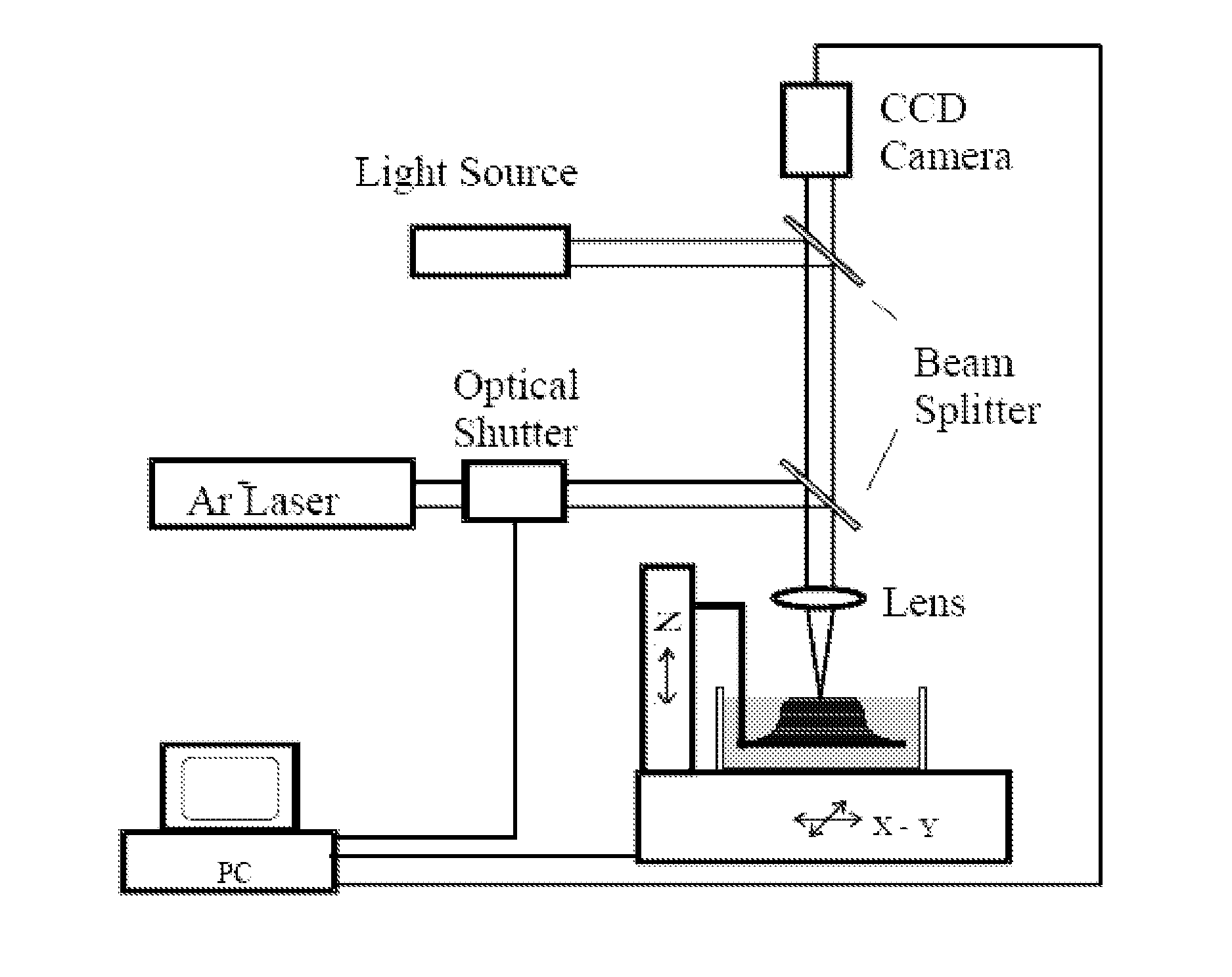
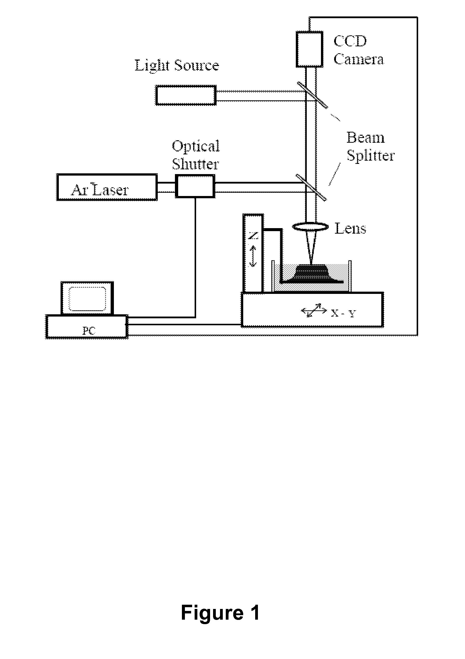
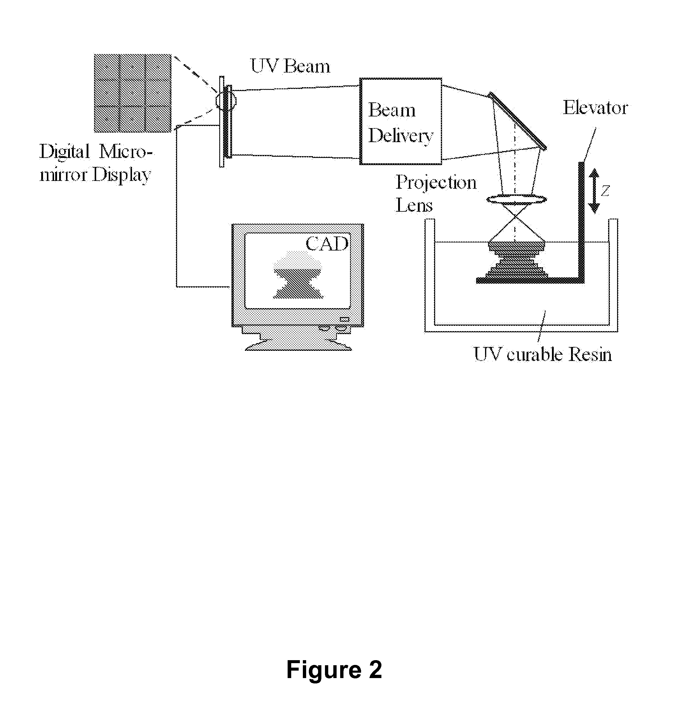
[0135]Stereolithography (SL) is a powerful fabrication technology which utilizes light-induced polymerization of liquid monomers to form complex three-dimensional shapes for a variety of purposes. Stereolithography is capable of fabricating complex three-dimensional solid structures using only light as a writing tool and liquid polymer as a base material. Stereolithography is a member of a larger class of photolithography technologies used for making silicon circuits and MEMS devices in the sense that all use light as a writing instrument.

[0136]The advent of microelectromechanical systems (MEMS) was brought about by the application of IC fabrication technology to the unique manufacturing challenges that exist at the microscale. The broad success of MEMS-based approaches has resulted in a multitude of new microsystems spanning a diverse range of applications from automobiles to biomedicine to counterterrorism. Despite the success of mass fabricat...

example 2

Enhanced Microstereolithography Via Electrowetting-Induced Surface Flattening of a Two Fluid Interface

[0187]One of the major hindrances to the progress and eventual commercialization of microstereolithography technology is the long dwell times required for viscous polymers between fabrication of successive layers; the viscous forces of the heavier polymers resist the flattening efforts of gravity.

[0188]One potential solution for this problem involves constraining the surface of the liquid using a transparent plate. The plate, if positioned slightly below the liquid surface, would ensure a flat liquid surface and a uniform layer thickness without the long dwell times required by the free surface approach. However, as described by Ikuta, there are serious obstacles to this approach due to secondary polymerization of the resin on the underside of the plate [35]. In short order secondary polymerization on the plate's surface renders it too opaque to allow the light to pass through it. A...

example 3

Modeling Biological Tissue

[0244]If the structure and function of biological systems can be better understood, their engineering knowledge can be more effectively utilized to serve humanity's needs. The most effective guides to utilizing the engineering designs of living systems are the living systems themselves.

[0245]One of the challenges involved in accurately modeling biological systems is reproducing the fine shades of density, structure, and function present in biological tissues. Tuning the properties of different regions of the tissue samples is critical to proper modeling, yet very difficult to accomplish using traditional manufacturing techniques. Here the modeling of biological systems in PEDGA monomers and the ability of microstereolithography to “tune” the diffusion properties of such models are demonstrated. With these tools in hand more accurate models of biological structures can be realized, and their unique properties may be utilized to serve a broad range of applica...


PUM


Abstract

In an aspect, the present invention uses projection micro stereolithography to generate three-dimensional microvessel networks that are capable of supporting and fostering growth of a cell population. For example, provided is a method of making a microvascularized bioreactor via layer-by-layer polymerization of a photocurable liquid composition with repeated patterns of illumination, wherein each layer corresponds to a layer of the desired microvessel network. The plurality of layers are assembled to make a microvascular network. Support structures having different etch rates than the structures that make up the network provides access to manufacturing arbitrary geometries that cannot be made by conventional methods. A cell population is introduced to the external wall of the network to obtain a microvascularized bioreactor. Provided are various methods and related bioreactors, wherein the network wall has a permeability to a biological material that varies within and along the network.

Description

CROSS-REFERENCE TO RELATED APPLICATIONS[0001]This application claims the benefit of priority to U.S. Provisional Patent Application 60 / 974,699 filed Sep. 24, 2007 which is hereby incorporated by reference in its entirety to the extent not inconsistent with the disclosure herein.BACKGROUND OF THE INVENTION[0002]There is a great deal of interest in systems that provide the capacity for expansion of a cell population for a number of reasons. First, there is increasing demand for cell secreted products, including mammalian cell secreted products, that can be of benefit for human use. The products include monoclonal antibodies, vaccines, hormones, growth factors, enzymes and other recombinant DNA products. For any of these products to be of commercial use, the product must be economically produced. Accordingly, systems capable of culturing relatively dense three-dimensional cell cultures to provide higher concentration of the product are desirable. Similarly, there is increasing interest...

Claims


Application Information

Patent Timeline
IPC IPC(8): C12M3/00G03F7/20C12P1/00G01D18/00
CPCB01L3/502707B81B2201/058C12M23/16B81C1/00119B81C99/0095B81B2201/06B33Y10/00
Inventor FANG, NICHOLAS X.XIA, CHUNGUANGCOX, ANDREW
Owner THE BOARD OF TRUSTEES OF THE UNIV OF ILLINOIS
Learn More