
Long life high efficiency neutron generator

a high-efficiency, long-life technology, applied in nuclear reactors, nuclear targets, greenhouse gas reduction, etc., can solve the problems of short life, low efficiency, increased scrutiny, etc., and achieve the effect of low efficiency, large size and high cos

Active Publication Date: 2011-02-24
STARFIRE IND LLC
View PDF23 Cites 71 Cited by
  • Summary
  • Abstract
  • Description
  • Claims
  • Application Information

AI Technical Summary

Benefits of technology

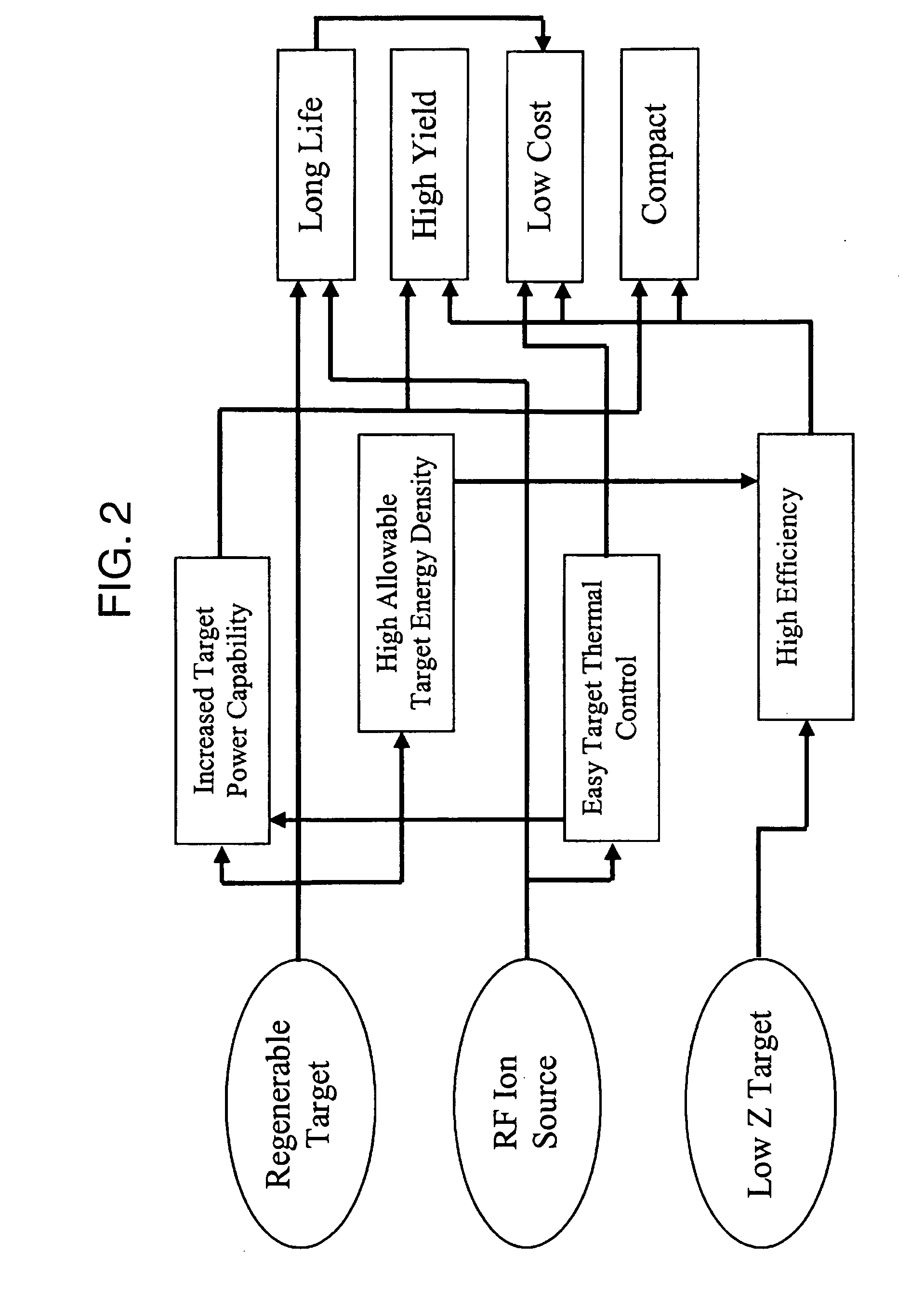
[0007]As summarized in FIG. 2, an innovation for the device as a whole results from the combination of a regenerable low-Z (low atomic number) target for long life and high efficiency with an RF ion source that allows compact and easy thermal management with long life. These factors combine to increase yield and decrease cost. Improved efficiency and better thermal properties allow the source size to be decreased, allowing its use in applications that require small sources, such as small-diameter boreholes (<2 inches). Such a compact and inexpensive source could also be used in laboratory and academic settings for geoscience and other non-destructive testing applications, such as online bulk materials analysis (such as for coal and cement mining), soil analysis, borehole logging analysis, and security screening systems, and others. These innovations would allow for radioactive neutron sources in industry to be replaced with FNGs in a wide variety of applications, improving safety and broadening the types of analysis that can be accomplished. Additionally, innovative designs have been made to combine the necessary components and subsystems of an FNG in highly efficient and cost-effective ways.
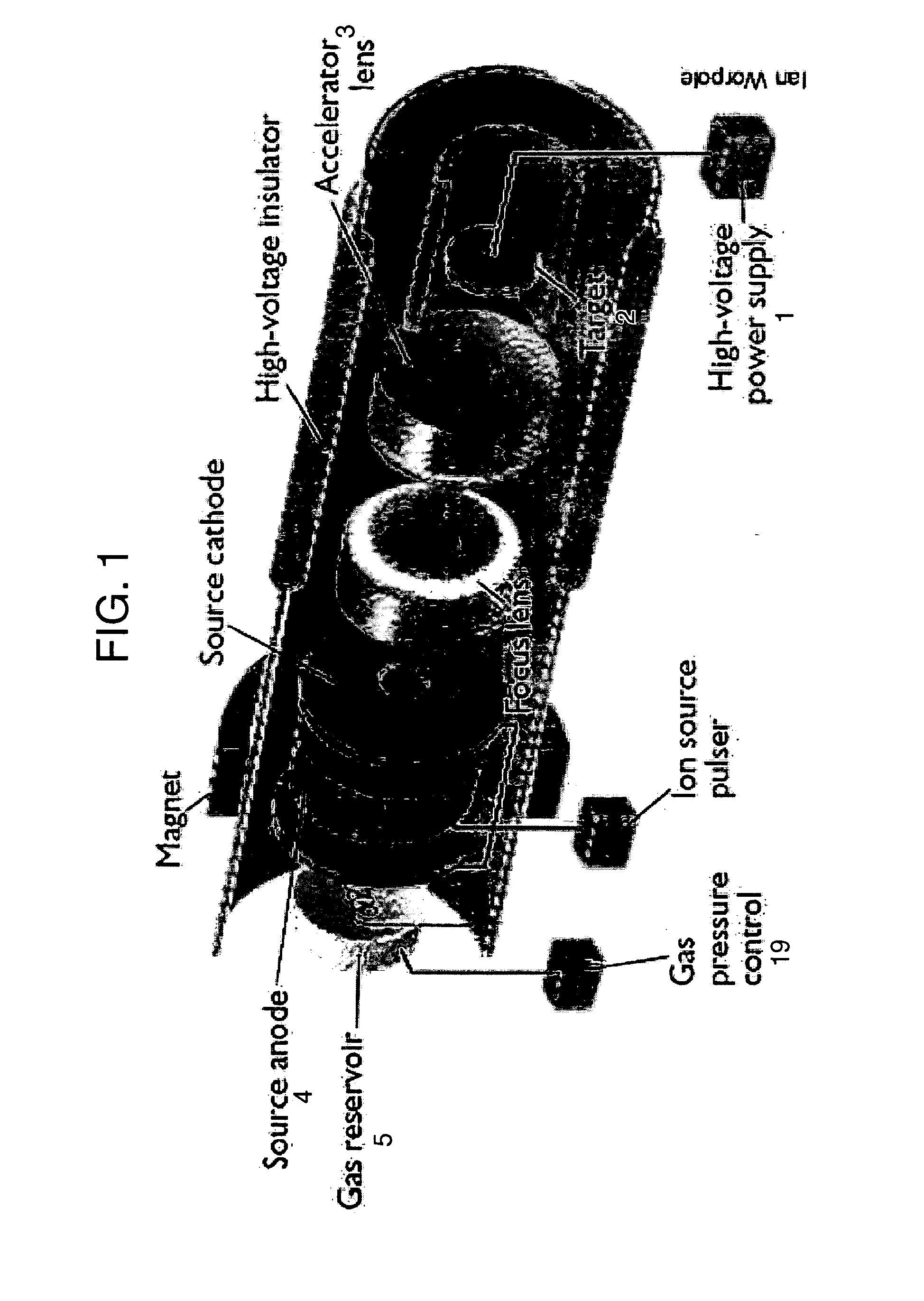
[0008]Traditional ion sources such as a Penning ion source use active filaments or multiple plasma-contacting electrodes to create ionizations. These components eventually wear out, causing a system failure and limiting lifetime. Aspects of the present invention include a radio frequency (RF) or microwave ion source which uses no electrodes and has the advantage of generating high fractions of monatomic ions. An RF ion source uses a coiled, or shaped ribbon, antenna on the outside of the system wall / insulator that deposits electromagnetic power into the gas, causing ionizations, dissociations and plasma sustainment. While current FNGs bias their target to a large negative voltage to create the acceleration field, aspects of the invention use another inherent advantage of the RF ion source and raise the voltage of the plasma while maintaining the RF hardware and the target at or near ground potential. This is possible because the RF couples its energy through electromagnetic fields instead of physical electrodes in contact with the plasma. Using a grounded target resolves several design concerns, such as thermal control of the target and target diagnostics. This has the additional benefit of allowing the neutron source—the target—to be closer to the materials being analyzed due to lack of the necessary high-voltage standoff hardware, resulting in higher neutron fluxes at the material of interest for the same source output. The RF or microwave ion source also allows for relatively easy multi-source configurations where multiple ion beams can be extracted from a common plasma region to produce a mutli-point neutron source.
[0009]In addition to continuous operation, several options exist for pulsed operation. One option is to pulse an extraction electrode. This has the benefit of requiring relatively low voltage pulses, but would still require a high-voltage pulse forming network. Another option is to use a pulse transformer to directly pulse the high-voltage power. A simple schematic of a transformer-based pulsing system is shown in FIG. 7. This exemplary method has the advantage of allowing low-voltage pulse forming network elements and a low-voltage (lower cost) DC power supply. The use of beam-bunching electrodes can further shorten pulses of a system down to the nanosecond range. The choice of pulsing technique depends on the cost, size and the needs of the end-user. All of these techniques are capable of achieving pulse lengths in the range of 0.1-10,000 μs with a corresponding broad range of repetition rates, depending on the duty factor of the pulse system.

Problems solved by technology

Radioisotopes, such as 252Cf, are currently used in the academic and industrial markets, but are under increasing scrutiny due to homeland security concerns.
Several FNG technologies are available in the marketplace, but are hampered by high cost, large size, low efficiency, and short lifetime, typically making them unsuitable for broad use.
These components eventually wear out, causing a system failure and limiting lifetime.

Method used


Image

  • Long life high efficiency neutron generator
  • Long life high efficiency neutron generator
  • Long life high efficiency neutron generator

Examples


Embodiment Construction

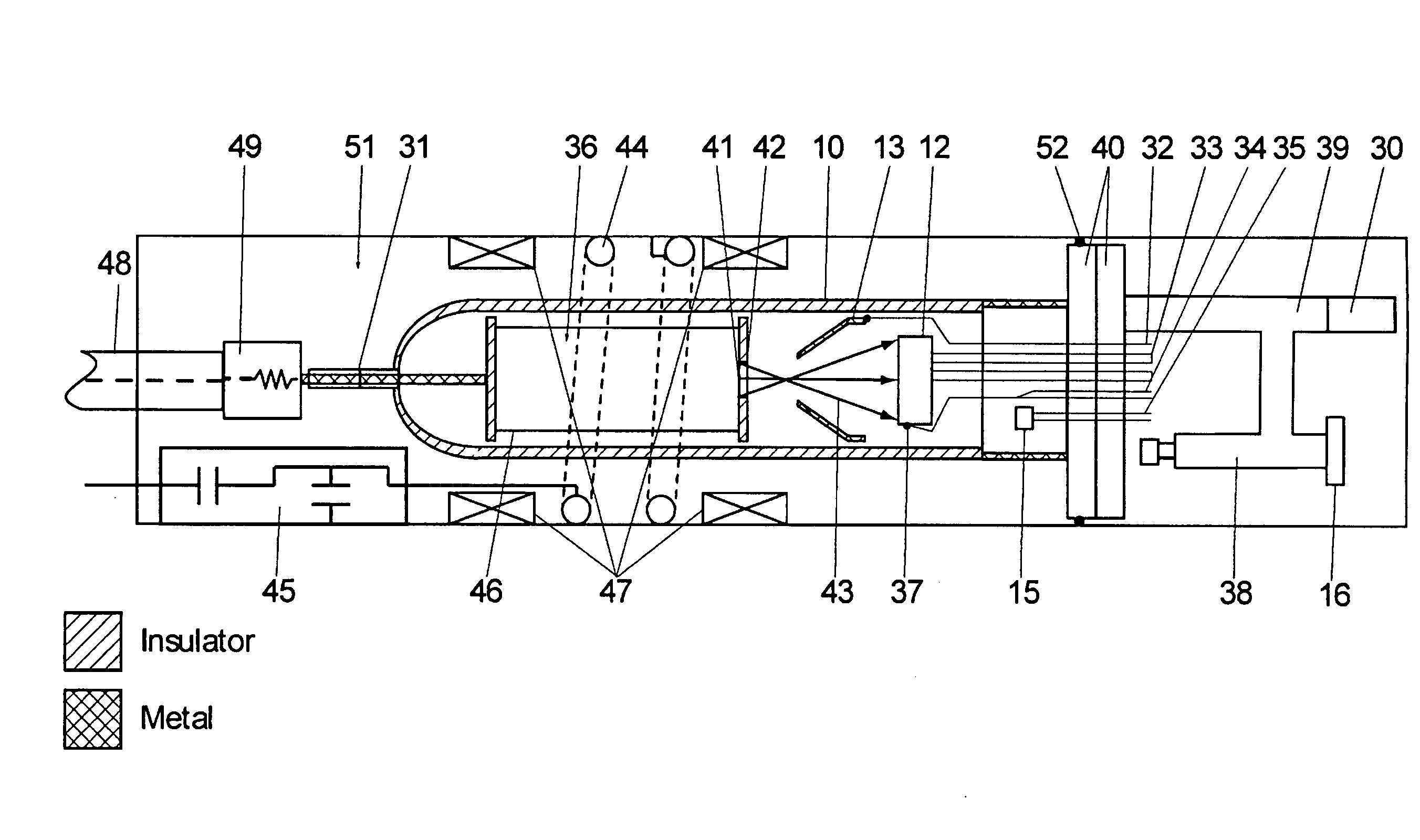
[0018]FIG. 3 shows the layout for the “neutron tube” core of a generic embodiment of the invention. A vacuum vessel 10 forms the main structure. Inside are the three primary electrodes: the ion source (anode) 11, neutron-producing target (cathode) 12, and electron suppressor electrode 13. The ion source power supply 14 creates AC, DC, or radio frequency / microwave power depending on the type of ion source 11 used. A non-evaporable getter 15 is used to control gas pressure via heating.

[0019]In one possible embodiment shown in FIG. 4, the vacuum vessel 10 is a sealed tube made of a combination of conductor and insulator. If one end of the neutron tube is at low voltage, it can easily be made of conductive material facilitating fabrication and installation of electrical feedthroughs. Conductors used include primarily aluminum, stainless steel, copper, and kovar. Stainless steel and iron are minimized to reduce gamma signature in NAA applications. Glass, quartz, or alumina (or similar ce...


PUM


Abstract

The design of a compact, high-efficiency, high-flux capable compact-accelerator fusion neutron generator (FNG) is discussed. FNG's can be used in a variety of industrial analysis applications to replace the use of radioisotopes which pose higher risks to both the end user and national security. High efficiency, long lifetime, and high power-handling capability are achieved though innovative target materials and ion source technology. The device can be scaled up for neutron radiography applications, or down for borehole analysis or other compact applications. Advanced technologies such as custom neutron output energy spectrum, pulsing, and associated particle imaging can be incorporated.

Description

CROSS-REFERENCE TO RELATED APPLICATIONS[0001]This patent application claims the benefit of U.S. Provisional Patent Application No. 61 / 031,899, filed Feb. 27, 2008, 61 / 031,908, filed Feb. 27, 2008, 61 / 031,912, filed Feb. 27, 2008, 61 / 031,916 filed Feb. 27, 2008, and 61 / 031,921, filed Feb. 27, 2008, all of which are herein incorporated by reference in their entireties, without exclusion of any portion thereof, whether specifically referenced herein or otherwise.BACKGROUND OF THE INVENTION[0002]Radioactive nuclear sources are currently used in industry in a variety of places, including on-line elemental analysis of mining, coal, and cement feedstocks, and sub-surface scanning (e.g. soil composition analysis and landmine detection). The traditional neutron source has been a radioisotope such as 252Cf or Am-Be. Radioisotopes are always on, require shielding, limit types of analysis (e.g. no pulsing or time-of-flight), and pose a personnel hazard during manufacturing and assembly, as well...

Claims


Application Information

Patent Timeline
Patent Type & Authority Applications(United States)
IPC IPC(8): G21B1/00G21B1/17G21B1/05
CPCH05H3/06G21B1/19G21G4/02H05H6/00Y02E30/10
Inventor STUBBERS, ROBERT ANDREWJURCZYK, BRIAN EDWARDALMAN, DARREN ADAMCOVENTRY, MATTHEW DAVIDSCHAUS, MICHAEL JEROME
Owner STARFIRE IND LLC
Learn More