
Silicon titanium oxide coating, coated article including silicon titanium oxide coating, and method of making the same

a technology of silicon titanium oxide and coating, applied in the direction of instruments, optical elements, transportation and packaging, etc., can solve the problems of low deposition rate of metallic alloy metal targets in reactive sputtering, limited use of alloy metals as metal sputtering targets, and difficulty in mixing gas when sputtering metal or si targets, etc., to achieve lower sputtering rate, lower refraction index (n) value, and high refraction index

Active Publication Date: 2011-04-07
GUARDIAN GLASS LLC
View PDF10 Cites 27 Cited by
  • Summary
  • Abstract
  • Description
  • Claims
  • Application Information

AI Technical Summary

Benefits of technology

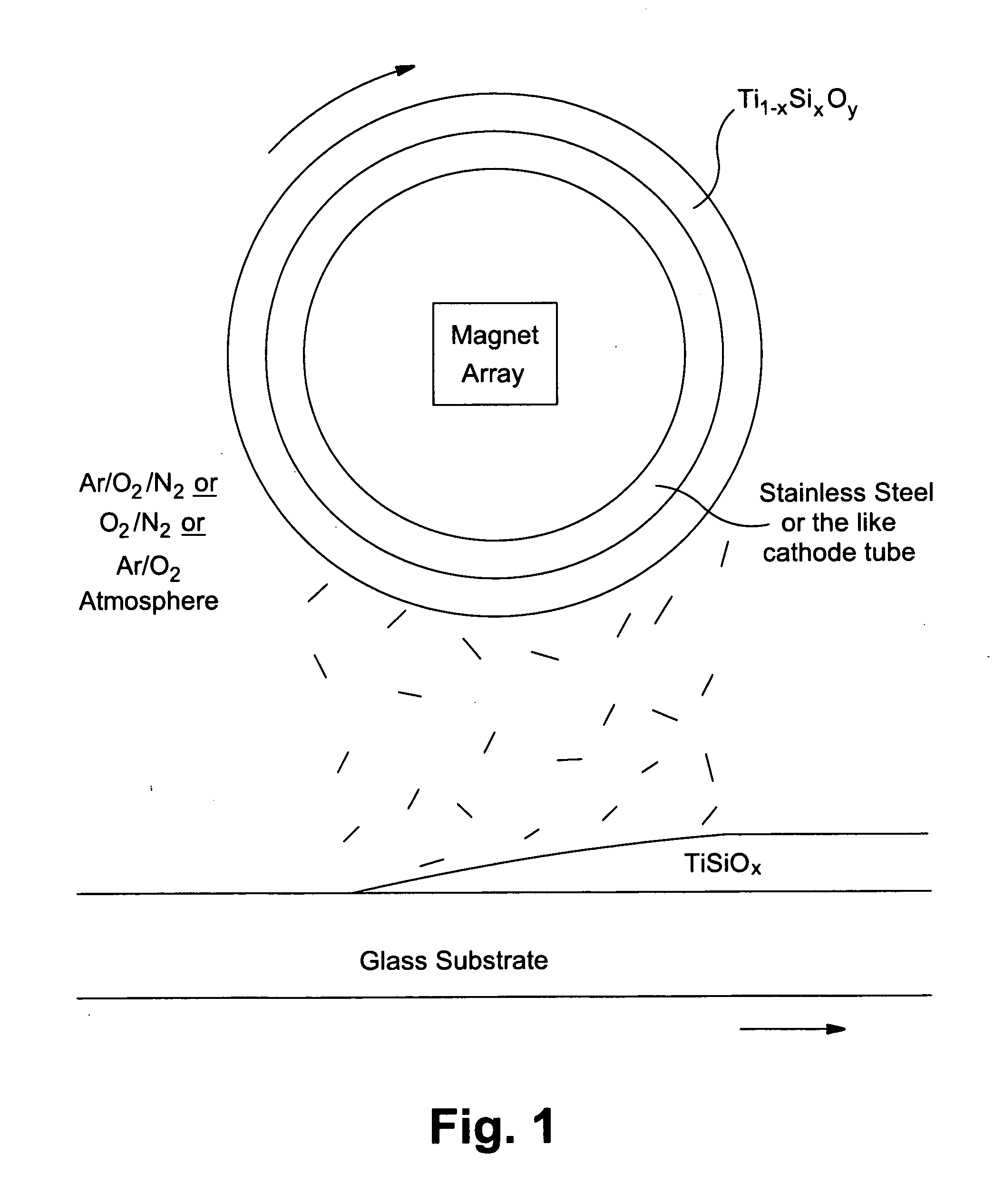
[0006]There are different types of sputtering targets, such as planar magnetron and cylindrical rotatable magnetron targets. Planar magnetrons may have an array of magnets arranged in the form of a closed loop and mounted in a fixed position behind the target. A magnetic field in the formed of a closed loop is thus formed in front of the target. This field causes electrons from the discharge to be trapped in the field and travel in a pattern which creates a more intense ionization and higher sputtering rate.
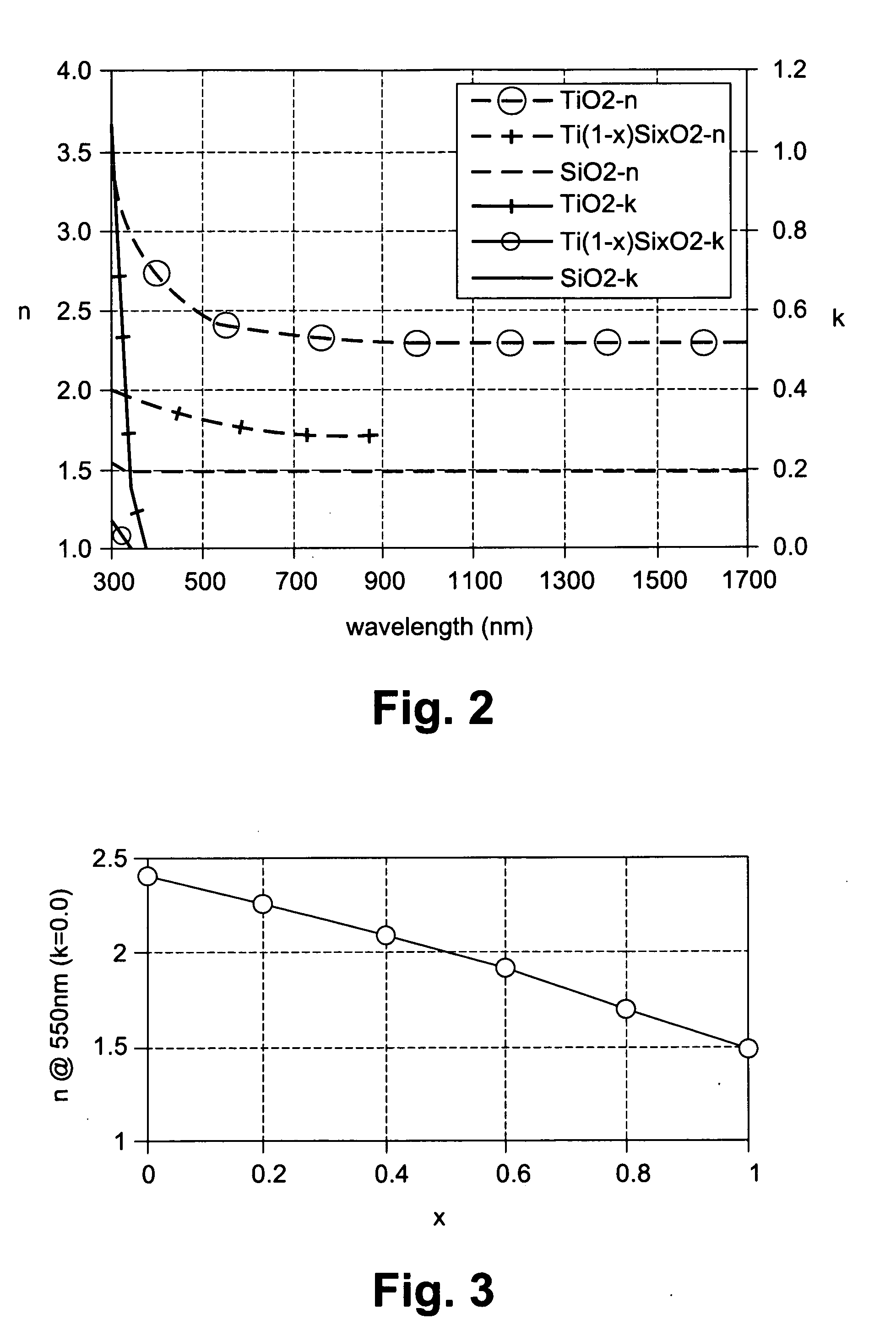
[0008]Materials such as tin oxide, zinc oxide, and silicon nitride have an index of refraction (n) around 2, where SiO2 has an index of refraction (n) of about 1.5 and TiO2 has an index of refraction of about 2.4. There exists a need for materials, that can be used in low-E, transparent conductive, and / or AR coatings, that have an index of refraction (n) between these values (e.g., from about 1.6 to 1.9, or 2.1 to 2.3, for example). Materials with such index values would be advantageous in that they could be used to further reduce reflection in coated articles using low-E and / or AR coatings having the same. Alloys, mixes of reactive gases, or combinations of both alloys and mixtures of reactive gases may be used to generate thin films having desired properties that cannot be achieved using a single elemental metal approach, or a pure oxide approach.
[0014]The combination of Ti and Si in the target is advantageous in that Si and Ti form a suitable alloy. In certain example embodiments, when a ceramic target including Ti and Si is used, the amounts of Ti and Si can be varied to allow the desired index (n) value to be obtained in the resulting layer. Moreover, the ceramic nature of the sputtering target is advantageous in that it permits higher sputtering rates to be achieved. The oxygen in the target is stoichiometric (or close to stoichiometric) in certain example embodiments of this invention. Further, in certain example embodiments, the silicon oxide in the target has a higher sputter rate than the titanium oxide in the target. Therefore, in certain example embodiments, the ratio of Si to Ti in the film will be higher than the ratio of Si to Ti in the target itself In other example embodiments, a titanium silicon oxide-inclusive layer may be formed through use of a metallic target, sputtered in the presence of oxygen and / or other gases.

Problems solved by technology

The approach of using alloy metals as metal sputtering targets is limited by achievable small ranges of solid solution that restrict the ratio amount different materials.
Metallic alloy metal targets also face low deposition rate problems in reactive sputtering when full oxide and / or nitride films are desired.
The approach of mixing gases when sputtering metal or Si targets is also problematic.
However, unfortunately, the conventional way of doing this is to use a Si or Al target and vary the gas flows of nitrogen and oxygen to gain the desired oxygen to nitrogen ratio in the resulting layer to adjust its index of refraction value.
It is difficult to consistently adjust oxygen / nitrogen stoichiometry in the resulting layer in a desired manner by adjusting oxygen and nitrogen gas flows using a Si or Al target.
Oxygen and nitrogen gases have different weights and it is difficult to get consistent predictable results by varying oxygen and nitrogen gas flows when using a Si target in sputtering silicon oxynitride.
Therefore, layers deposited according to these methods may be difficult to make and / or have inconsistent and / or varying compositions.

Method used


Image

  • Silicon titanium oxide coating, coated article including silicon titanium oxide coating, and method of making the same
  • Silicon titanium oxide coating, coated article including silicon titanium oxide coating, and method of making the same
  • Silicon titanium oxide coating, coated article including silicon titanium oxide coating, and method of making the same

Examples


Embodiment Construction

[0031]Performance of optical coatings such as low-E and / or antireflective (AR) coatings, especially multi-layered coatings for broadband applications, relies on precisely controlled layer thicknesses and optical properties (e.g., n and / or k) in each individual layer in the coating(s). Materials having unique properties, such as refractive index (n) and extinction coefficient (k), stress and adhesion to adjacent layers are chosen to optimize the coating performance with respect to reflection, color, durability, and / or the like. The target may be a rotating magnetron sputtering target in certain example embodiments although other types of target are also possible in other alternative embodiments. For example, a non-rotating target may be used instead and may be applicable to this invention. As an example, a drum coater may be designed in such a way that neither the target nor the drum holding the substrate rotates, but instead magnets in the target tube rotate.

[0032]Certain example em...


PUM

PropertyMeasurementUnit
thicknessaaaaaaaaaa
thicknessaaaaaaaaaa
thicknessaaaaaaaaaa

Abstract

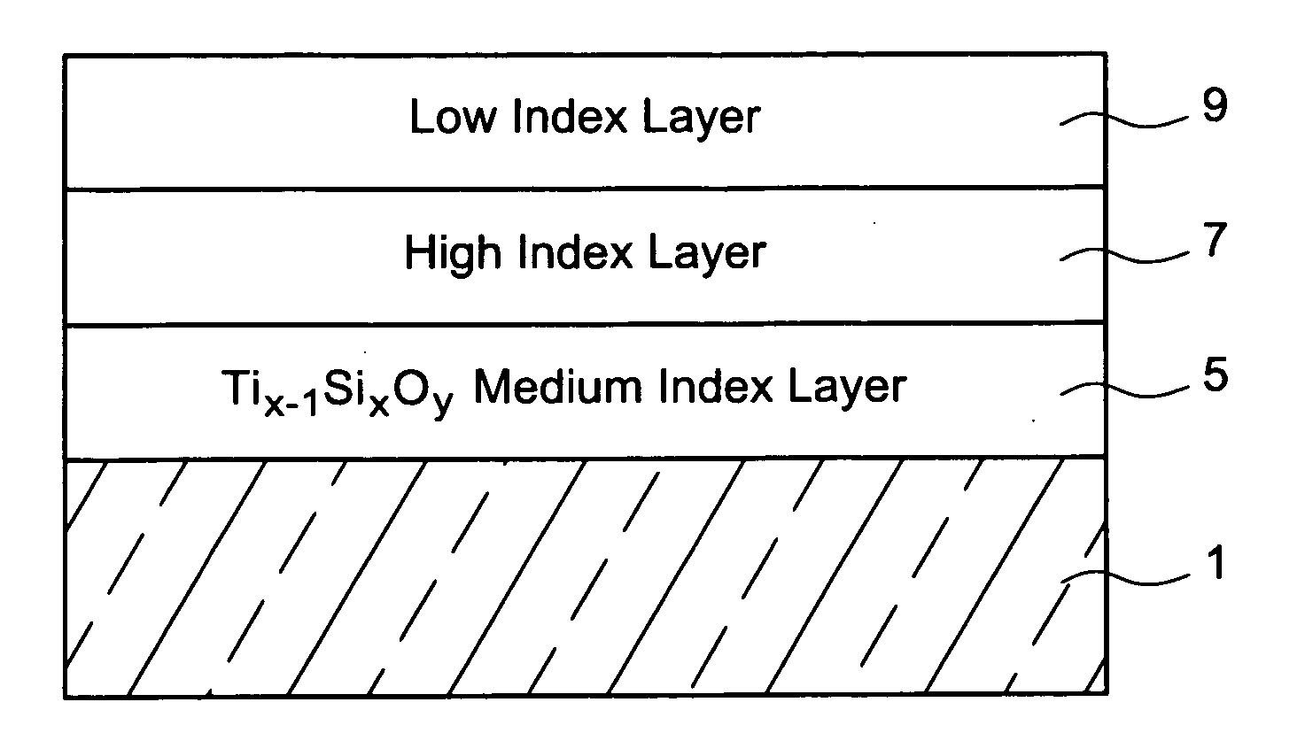
Certain example embodiments relate to a layer of or including Ti1-xSixOy and / or a method of making the same. In certain example embodiments, the Ti1-xSixOy-based layer may be substoichiometric with respect to oxygen. In certain example embodiments of this invention, the layer may include Ti1-xSixOy where x is from about 0.05 to 0.95 (more preferably from about 0.1 to 0.9, and even more preferably from about 0.2 to 0.8, and possibly from about 0.5 to 0.8) and y is from about 0.2 to 2 (more preferably from about 1 to 2, and even more preferably from about 1.5 to 2, and possibly from about 1.9 to 2). The layer may have an index of refraction of from about 1.6 to 1.9. The layer may also be used with a transparent conductive oxide in a transparent conductive coating.

Description

CROSS-REFERENCE TO RELATED APPLICATION[0001]This application is a continuation-in-part (CIP) of U.S. application Ser. No. 11 / 272,448, the entire contents of which are hereby incorporated by reference herein.FIELD OF THE INVENTION[0002]Certain example embodiments of this invention relate to a layer of or including Ti1-xSixOy and / or a method of making the same. In certain example embodiments, the layer may be deposited by a ceramic target. In certain example embodiments, the Ti1-xSixOy may be substoichiometric with respect to oxygen. In certain example embodiments of this invention, the layer may be of or include Ti1-xSixOy where x is from about 0.05 to 0.95 (more preferably from about 0.1 to 0.9, and even more preferably from about 0.2 to 0.8, and possibly from about 0.5 to 0.8) and y is from about 0.2 to 2 (more preferably from about 1.0 to 2, and even more preferably from about 1.5 to 2, and possibly from about 1.9 to 2). The layer may be deposited by a sputtering target comprising...

Claims


Application Information

Patent Timeline
Patent Type & Authority Applications(United States)
IPC IPC(8): C03C17/245C23C14/34B32B7/02B32B17/06
CPCC03C2217/73Y10T428/24975C03C2218/156C03C2217/213C03C2217/212G02B1/115C23C14/3414C03C2217/23C23C14/08C03C17/3417C03C2218/154C03C2218/155C03C17/3423C03C17/3435C03C2217/734C03C2217/94
Inventor LU, YIWEI
Owner GUARDIAN GLASS LLC
Learn More