[0015]The high
cooling rate and high solidifying rate have the effect of increasing the distribution coefficient to such an extent that micro segregations, i.e. microscopic separations, of the
molten material are largely avoided. The
molten material in the
weld metal solidifies dendritically, that is to say in a tree-like structure, the directions of growth of the dendrites varying along the welding trace, since the orientation of the possible directions of growth of the dendrites in relation to the
temperature gradient on the solidification front varies. That direction of growth with the smallest inclination in relation to the
temperature gradient or with the smallest
rate of growth prevails. In addition, seeds form ahead of the solidification front, which catches up with them during the solidification. These seeds initiate directions of
dendrite growth that are randomly distributed.
[0016]The method according to the invention is suitable, for example, for welding workpieces of a γ′-containing
nickel-based
superalloy by means of a welding filler which is a γ′-forming nickel-based
superalloy material. A high strength can be achieved in the
weld metal as a result of the use of filler of the same type and acceptable welding quality can be achieved, i.e. a very small number of cracks and a very low average crack length. As a result of the possibility of carrying out the
welding process at
room temperature with a
shielding gas atmosphere locally around the melting bath, the welding method according to the invention becomes highly cost-effective.
[0017]The method may be designed in particular as a build-up welding method, in which the welding filler is applied layer by layer. As this happens, the welding directions of successive
layers may be turned with respect to one another, particularly by 90°. Turning the welding direction of different
layers allows attachment defects between the
layers to be avoided, in particular whenever the heat input zone and the supply zone are also moved over the workpiece surface along the welding direction on a path that oscillates around the welding direction.
[0018]The irregularly distributed
dendrite orientation is mainly in the upper half of the welding trace. Therefore, in the method according to the invention, a previously applied layer is remelted in less than half its
layer thickness. In this case, the
crystal structure of the remelted regions is taken over during solidification. The small remelting depth ensures that the solidification front comes down on a region with irregularly distributed
dendrite orientations. In the case of multi-layer welding, this has the result that a polycrystal with grains of a very small
average diameter is generated. Grain boundaries generally represent a
weakness with respect to crack formation under transient stresses during the welding process or subsequent heat treatment. The low expansion of a
grain boundary in the plane and its irregular orientation in the
weld metal welded by the method according to the invention have the effect that the weld
metal is less sensitive to crack formation, so that the welding process can be carried out at
room temperature.
[0020]In the course of the welding method according to the invention, the application of the welding filler may be followed by a heat treatment. With a heat treatment adapted to the weld
metal, the desired γ′ morphology can be set. This serves for further improving the strength of the weld
metal.
[0023]The welding apparatus according to the invention makes it possible to carry out the welding method according to the invention by using a control program which contains the welding parameters for the welding process described in conjunction with the method, for instance the path of the relative movement between the heat source and the supplying device on the one hand and the workpiece on the other hand, the speed of the process, the
laser power, the
beam diameter, etc. The method parameters and mechanisms described in conjunction with the method help to suppress the formation of cracks, such as solidification cracks or remelting cracks, in the base material and the
molten material. This is also particularly the case whenever both the base material and the welding filler are γ′-forming nickel-based superalloys. This results in a quality of the welding that can be achieved with the method according to the invention and the welding apparatus according to the invention that is acceptable for structural welding, for instance for the purpose of repairing or joining in a highly stressed region of a
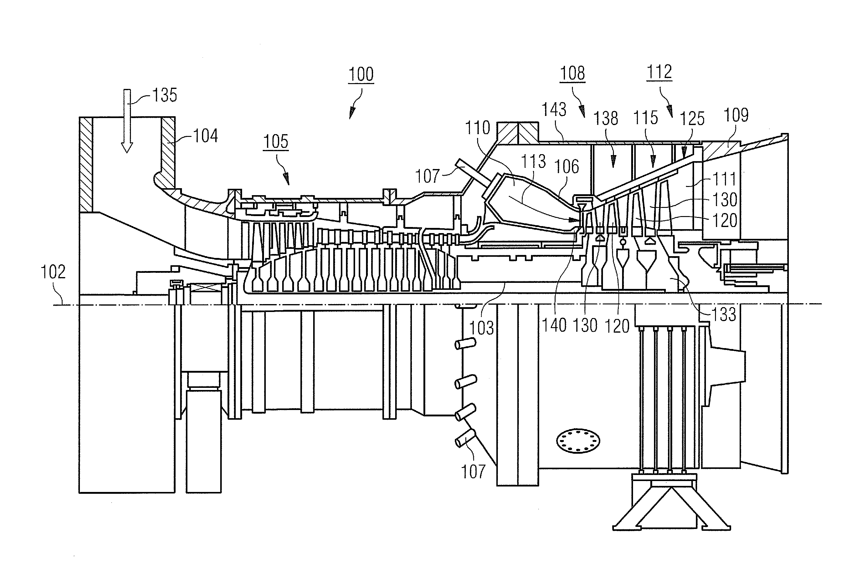
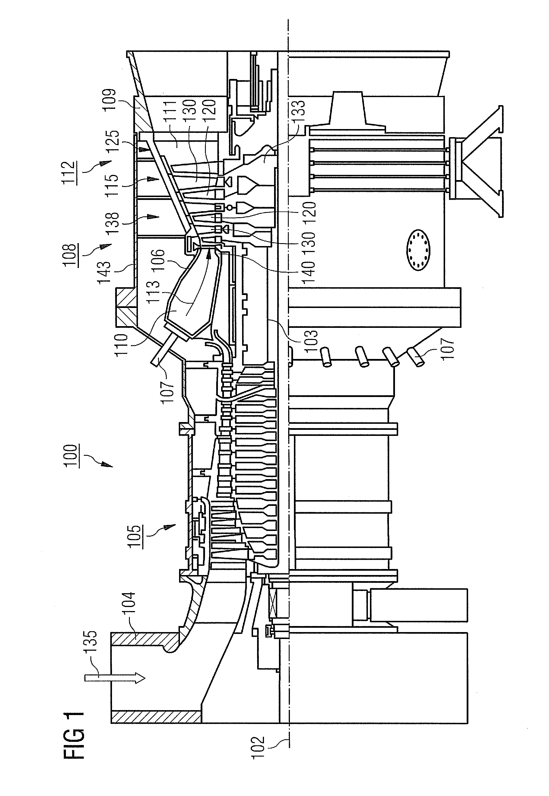
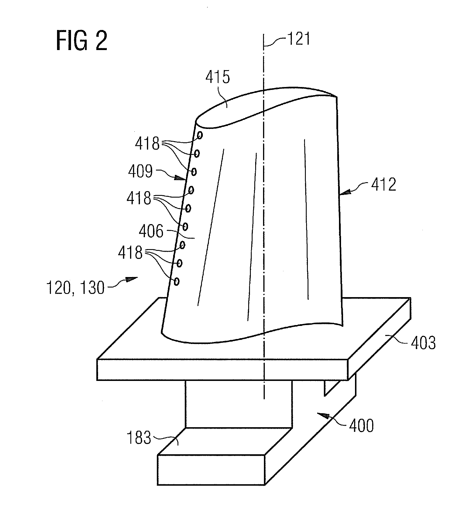
turbine blade or some other workpiece.

