Application of surface relief to spot welding electrodes

a surface relief and welding electrode technology, applied in the direction of electrical components, soldering equipment, manufacturing tools, etc., can solve the problems of unattractive sheet deformation around the weld, excessive indentation and/or unsightly sharp imprint on the steel surface, and undesirable whiskers or fingers of metal protruding from the sheet surface, so as to reduce production disruption and quickly and efficiently introduce specific patterns

Active Publication Date: 2011-04-28
GM GLOBAL TECH OPERATIONS LLC
View PDF13 Cites 19 Cited by
  • Summary
  • Abstract
  • Description
  • Claims
  • Application Information

AI Technical Summary

Benefits of technology

[0009]In many embodiments of the invention, the weld face image region may generally possess some symmetry, but typically it will not be features of circular symmetry centered about either the center of the weld face or the center of the axis of the electrode. It may be preferred to form such circular images by simple rotation of a shaped tool about a symmetry axis. In one embodiment, a durable protective mask is placed over the workpiece contacting surface of the electrode and an abrasive or mechanical material deformation and removal process is applied to the masked surface. The protective mask will prevent material deformation and removal from the masked areas and only the regions of the electrode unprotected by the mask will be exposed and subject to deformation and removal. Thus upon removal of the mask the desired pattern will be visible in the electrode.

Problems solved by technology

But these weld faces leave a sharp imprint on the steel surface that can have excessive indentation and / or an unsightly, uneven angle with the workpiece surface.
Such an electrode shape is prone to causing sheet deformation around the weld that is unattractive.
Also, metal expulsion from the sheet surface can lead to undesirable whiskers or fingers of metal protruding from the sheet surface.

Method used


Image

  • Application of surface relief to spot welding electrodes
  • Application of surface relief to spot welding electrodes
  • Application of surface relief to spot welding electrodes

Examples


first embodiment

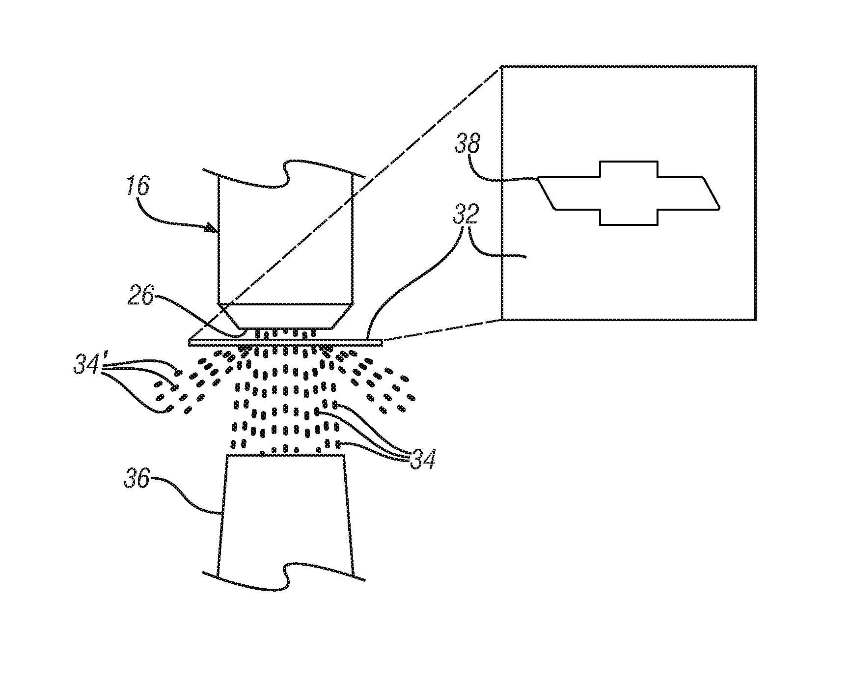
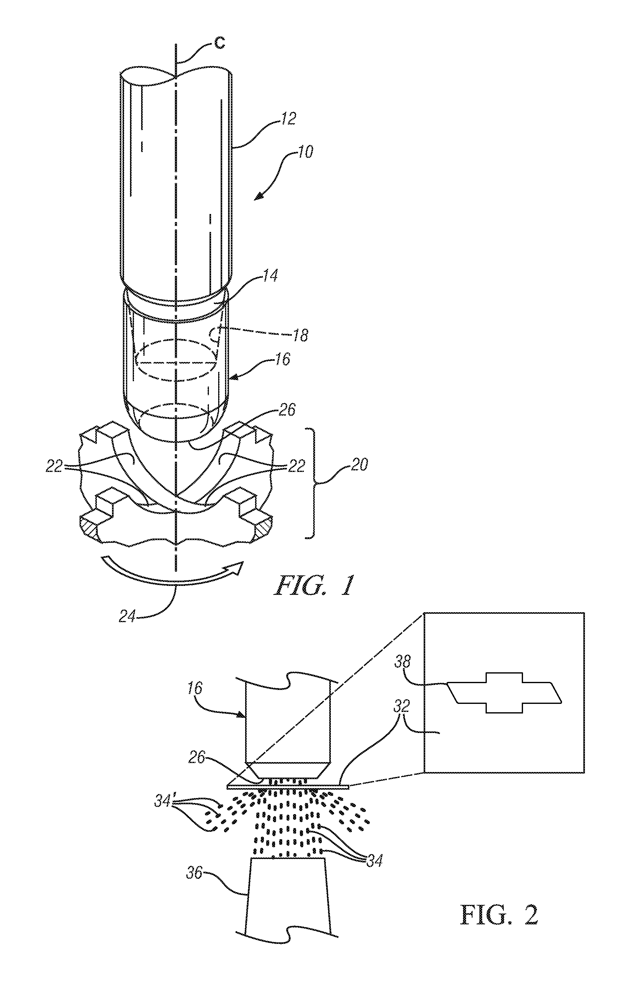
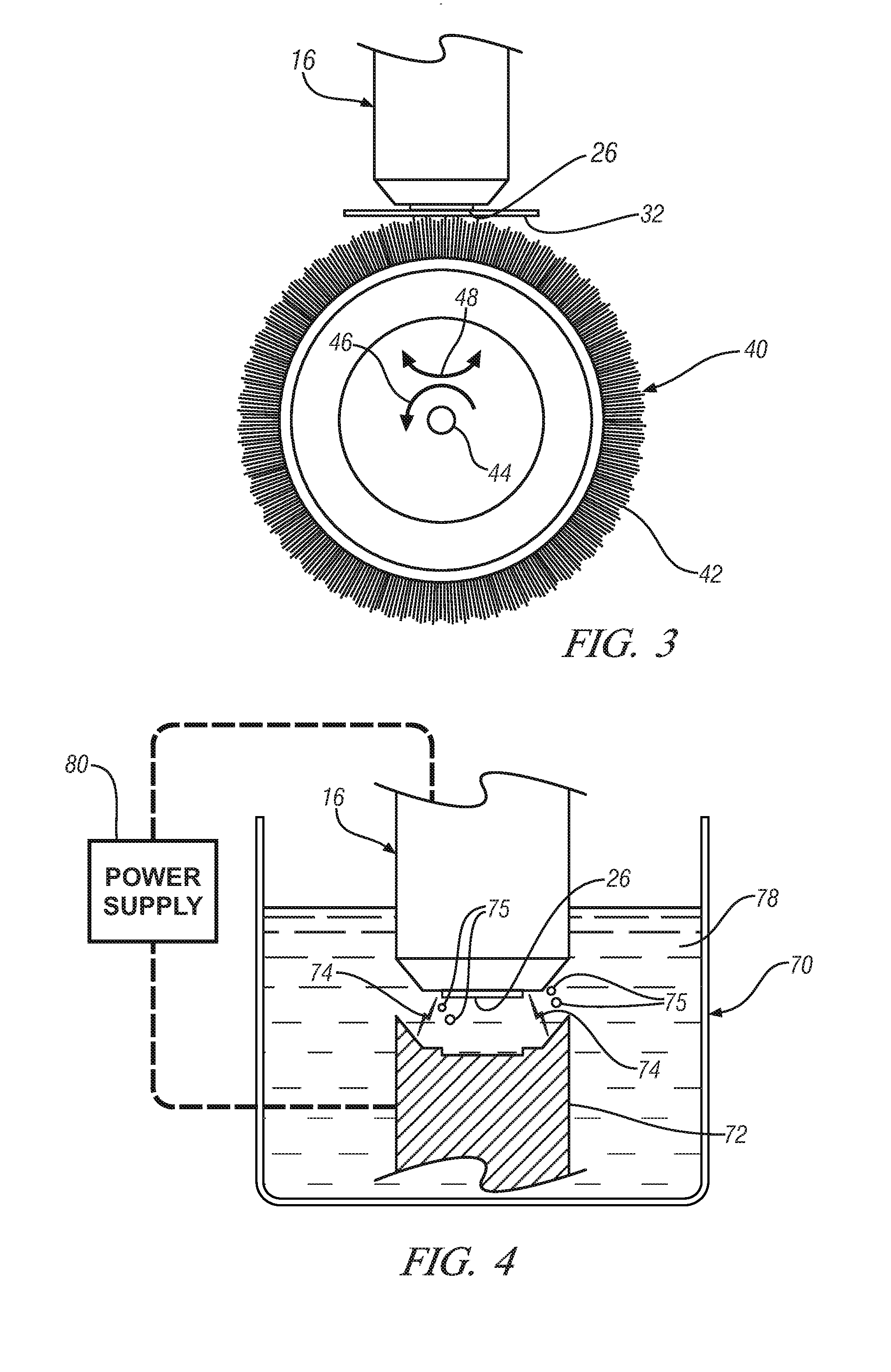
[0032]In a first embodiment, shown in FIGS. 2 and 3, an abrasive material removal process is used to create a 1 μm to 30 μm Ra rough surface. One such abrasive removal process, shown in FIG. 2, is grit blasting which may be performed using sand or steel grit media propelled against the surface by means of a high pressure (50 to 150 pounds per square inch) gas flow. Alternatively the cap may be brushed with stainless steel wire or silicon carbide-impregnated nylon brushes as shown in FIG. 3. Independently of the abrasive removal process selected, a mask with suitably-shaped opening is interposed between the abrasive medium and the weld cap. The mask will partially restrict access of the abrasive to the cap and thereby ensure that the abrasive process will create the desired form on the weld cap. Such a mask is usually used where the weld face presents a uniform composition across the face to the abrasive removal process.

[0033]In FIG. 2, electrode 16 is subjected to a stream of abrasi...

second embodiment

[0036]In a second embodiment, shown in FIG. 4, the pattern is imparted by electrical discharge machining and is capable of developing patterns with substantial differences in elevation on the electrode. An overview of the process is indicated at 70. By immersing the workpiece-contacting surface of the electrode in a bath of circulating (circulation system not shown) liquid dielectric 78, for example kerosene, and applying an increasing electrical potential, generated by power supply 80, between the electrode and a tool, an electrical discharge 74 will result. This discharge will vaporize a portion of the electrode 16 and a portion of the tool 72. However by fabricating the tool of a material with a high melting point and thus a high vaporization temperature, such as graphite or any of the refractory metals, the bulk of the vaporization will occur at the lower melting point copper-based electrode. This will introduce small particles of condensed copper-based alloy 75 into the electro...

third embodiment

[0037]In a third embodiment, illustrated in FIG. 5, the desired pattern may be imparted to the electrode by a mechanical upsetting process resulting from contact with a die as shown at 60. The electrode 16 is deformed by contact with rigid tool 62. Thus, the inverse geometry of the contact surface 66 of tool 62 is transferred to workpiece-contacting surface 26 of electrode 16. The required contact pressure P between the tool and the electrode may be generated by the weld apparatus or externally generated, for example by electromagnetically or explosively accelerating a compact tool electromagnetically to impact the electrode (not shown).

[0038]Preferably the electrode 16 will be heated to a temperature sufficient to reduce its flow stress prior to upsetting, for example by exposure to a tool 62 which has been heated by heater elements 64. Alternatively the electrode may be heated by passage of electric current through the electrode. An appropriate upsetting temperature will be alloy ...


PUM

PropertyMeasurementUnit
temperatureaaaaaaaaaa

Abstract

The workpiece-contacting surface of the spot welding electrode may be suitably modified to incorporate a desired shape or form, generally comprising a depressed region outlining a recognizable shape, to form aesthetically-pleasing or functional features in the surface of a workpiece during resistance spot welding. Methods for creating the desired form in the spot welding electrode including abrasion, upsetting, and electrical discharge machining are disclosed. Preferably the electrode face is shaped and subsequently redressed during welding operations at the welding station.

Description

TECHNICAL FIELD[0001]This invention relates to methods for the application of a surface relief image or pattern on the welding face of a spot welding electrode so that a functional and aesthetically pleasing pattern may be repeatedly imparted to surfaces of spot welded workpieces. In many embodiments, this invention pertains to the formation of such images on the welding face where the image does not consist of features of circular symmetry centered about the weld face of the electrode.BACKGROUND OF THE INVENTION[0002]Resistance spot welding is a joining process that is used in many manufacturing processes for making automotive vehicle bodies and other vehicle members. For example, it is used for welding sheet metal inner and outer closure panels (like doors, decklids, liftgates, and hoods) to one another by a series of spot welds at suitable locations on the workpieces. The sheet metal material may be a steel alloy, a galvanized steel, an aluminum alloy, a magnesium alloy, or the l...

Claims


Application Information

Patent Timeline
Patent Type & Authority Applications(United States)
IPC IPC(8): B23K11/00B24B1/00B23H1/00
CPCB23K11/115B23K11/3009B23K2201/007B23K35/0205B23K11/3063B23K2101/007B23K35/402
Inventor SCHROTH, JAMES G.SIGLER, DAVID R.
Owner GM GLOBAL TECH OPERATIONS LLC
Why Eureka
Try Eureka