Apparatus and method for dispersive fourier-transform imaging

a fourier-transform imaging and apparatus technology, applied in the field of optical imaging, can solve the problems of limiting the number of scans per second, the image frame rate the speed of the fastest barcode reader is limited to a rate of about one thousand scans, so as to improve the strength of the signal, improve the effect of performance and high total dispersion

Inactive Publication Date: 2011-07-14
RGT UNIV OF CALIFORNIA
View PDF24 Cites 26 Cited by
  • Summary
  • Abstract
  • Description
  • Claims
  • Application Information

AI Technical Summary

Benefits of technology

[0033]The present invention relies on the use of internal amplification within the dispersive element for overcoming the tradeoffs on sensitivity, the number of image pixels, and scanning speed. The above trade-off is overcome by compensating for losses in the dispersive element. Toward optimizing performance, the amplification is performed in the dispersive fiber to increase the strength of the signal reflected back from the barcode. Internal amplification in a dispersive element has previously been demonstrated in our laboratory in relation to real-time Raman and absorption spectroscopy, as well as a femtosecond digitizing. This amplification is applied in the present invention toward optimizing one or more barcode scanner embodiments.
[0034]The desirable features for a dispersive element are high total dispersion, low loss, large optical bandwidth, smooth dispersion over the bandwidth, and commercial availability. Dispersive fibers such as dispersion compensation fiber (DCF) offer an optimum combination of these parameters, although there are other options such as chirped fiber Bragg gratings (CFBG). While CFBG are more compact than DCF, the latter can also function as a Raman amplifier to c

Problems solved by technology

Although barcode readers are useful for keeping track of a large number of items, the conventional barcode technology has its limitation in speed when it requires tracking of a considerably large number of items (e.g., on the order of millions) due to their slow reading and decoding process.
Even the fastest barcode reader is limited to a rate of about one thousand scans per second.
The speed limitation in scanners is largely in response to the need of scanning the source light across the barcode, while in imaging readers the image frame rate limits the number of scans per second.
The speed limit of conventional barcode readers combined with the conventional digital signal processing prohibits one from tracking a considerably larger number of i

Method used


Image

  • Apparatus and method for dispersive fourier-transform imaging
  • Apparatus and method for dispersive fourier-transform imaging
  • Apparatus and method for dispersive fourier-transform imaging

Examples


embodiment 10

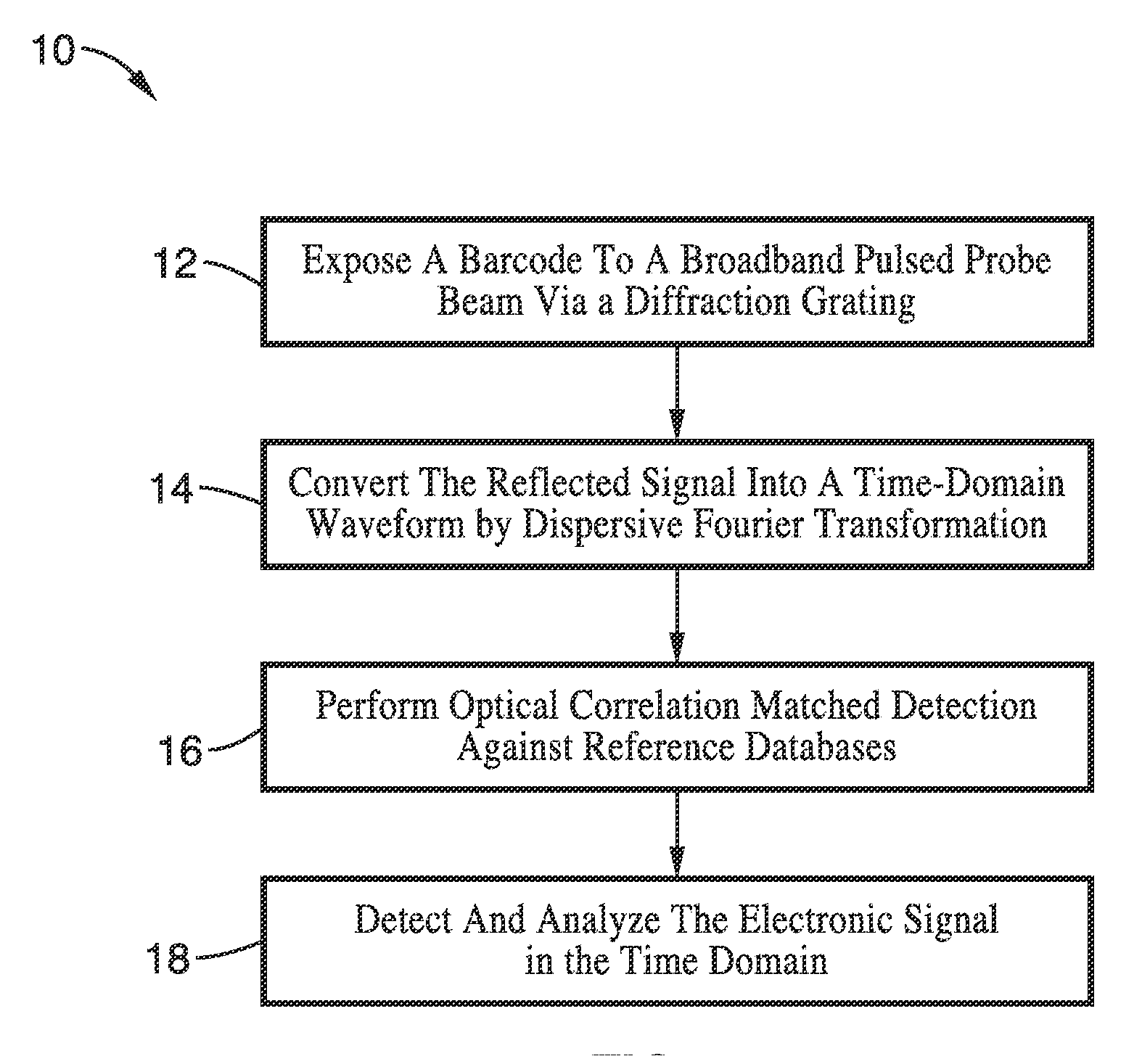
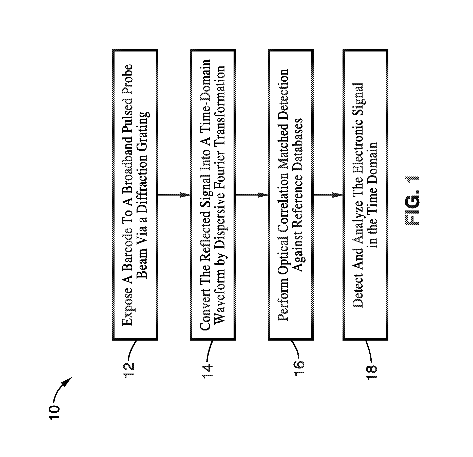
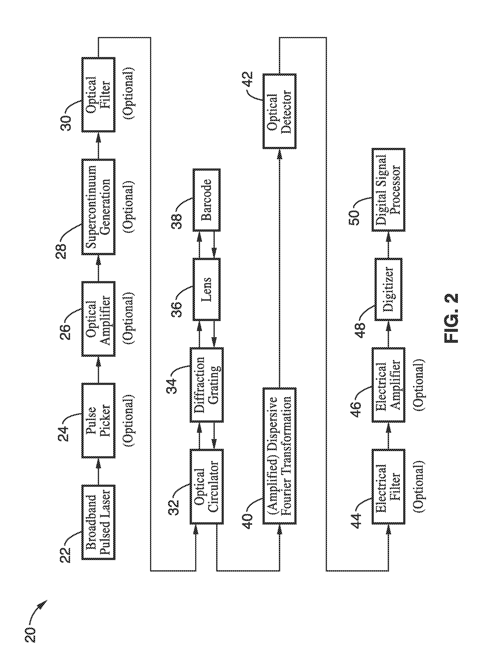
[0080]FIG. 1 is a method for dispersive Fourier-transform reflectivity measurement, summarizing the steps necessary for performing one- or two-dimensional barcode reading and optional correlation matched detection against known databases. According to this embodiment, a barcode is exposed to a broadband pulse through a diffraction grating at block 12, with the spatially dispersed spectrum being incident on the barcode. In block 14, the resulting reflected light from the barcode returns to the diffraction grating which reforms a pulse and is converted into a time-domain waveform by dispersive Fourier transformation. Then optional correlation matched detection against a reference database can be optically performed in block 16 upon the spectrally encoded barcode information by modulating it with an optical modulator fed by a pattern generator. The optical signal is detected by a photodetector in block 18 and its electronic signal is analyzed, such as by a digital signal processor, in ...

embodiment 1

[0126]2. An apparatus as recited in embodiment 1, wherein said responsive optical signal is created in response to optical energy which is reflected from the target to said means for dispersive Fourier-transformation, or optical energy that is transmitted through the target to said means for dispersive Fourier-transformation.

[0127]3. An apparatus as recited in embodiment 1, wherein said probe beam and said responsive optical signal are carried through free-air, optical fiber, or through a combination of free-air and optical fiber.

[0128]4. An apparatus as recited in embodiment 1, wherein said means for generating said broadband pulsed probe beam comprises a laser configured to generate pulses.

[0129]5. An apparatus as recited in claim 1, further comprising means for picking selected pulses from a train of pulses generated by said means for generating a broadband pulsed probe beam.

[0130]6. An apparatus as recited in embodiment 1, further comprising means for amplification and / or filter...


PUM


Abstract

A barcode reading apparatus and method in which the spectrum of a probe light is first Fourier-transformed into space, directed upon a barcode, and then Fourier-transformed converting the spectrally encoded barcode pattern to a time domain waveform. In one implementation, the Fourier transformation from the spectrum domain into a spatial domain is performed by a dispersive element, while the Fourier transformation from the spectrally encoded barcode pattern to a time domain waveform is performed by group-velocity dispersion (GVD). The temporally encoded barcode pattern is detected by a photodetector, digitized by a digitizer, and analyzed by a digital signal processor. The invention is applicable to a number of fields which involve the reading of one- and two-dimensional barcodes, displacement sensing, surface measurements, measurement of width and gap, flow cytometry, reading of optical media, presense or absence detection, and other related fields.

Description

CROSS-REFERENCE TO RELATED APPLICATIONS[0001]This application a 35 U.S.C. §111(a) continuation of, and claims priority to, PCT international application number PCT / US2009 / 051608 filed on Jul. 23, 2009, incorporated herein by reference in its entirety, which claims priority to U.S. provisional application Ser. No. 61 / 083,255 filed on Jul. 24, 2008, which is incorporated herein by reference in its entirety.[0002]The above-referenced PCT international application was published on Jan. 28, 2010 as PCT International Publication No. WO 2010 / 011875, and is incorporated herein by reference in its entirety.STATEMENT REGARDING FEDERALLY SPONSORED RESEARCH OR DEVELOPMENT[0003]This invention was made with Government support of Grant No. N66001-07-1-2007, awarded by the Department of Defense. The Government has certain rights in this invention.INCORPORATION-BY-REFERENCE OF MATERIAL SUBMITTED ON A COMPACT DISC[0004]Not ApplicableNOTICE OF MATERIAL SUBJECT TO COPYRIGHT PROTECTION[0005]A portion of...

Claims


Application Information

Patent Timeline
IPC IPC(8): G06K7/14G06F17/00G06Q90/00G01B11/14G06V30/224
CPCG06K7/14G06K7/10831G06K7/10712G06K7/1439G06V30/224
Inventor JALALI, BAHRAMGODA, KEISUKETSIA, KEVIN KIN-MAN
Owner RGT UNIV OF CALIFORNIA
Why Eureka
Try Eureka