
Capacitor manufacturing method

a manufacturing method and capacitor technology, applied in the manufacture of electrolytic capacitors, capacitor details, coatings, etc., can solve the problems of low productivity, deterioration of capacitor productivity, and affecting the performance of capacitors,

Inactive Publication Date: 2011-07-14
SHIN-ETSU POLYMER CO LTD
View PDF2 Cites 18 Cited by
  • Summary
  • Abstract
  • Description
  • Claims
  • Application Information

AI Technical Summary

Benefits of technology

The capacitor manufacturing method of the present invention enables a capacitor having a high withstand voltage, a high electrostatic capacitance and a satisfactorily small ESR to be manufactured simply and at a high level of productivity.

Problems solved by technology

However, in the manufacturing method disclosed in Patent Document 1, in which a conductive polymer layer is formed by chemical oxidative polymerization or electrochemical polymerization on the surface of the dielectric layer, a problem arises in that if thorough washing is not performed following the polymerization, then the withstand voltage tends to fall.
However, if thorough washing is conducted in order to prevent this type of problem from occurring, then the productivity of the capacitor tends to deteriorate.
Moreover, because the conductive polymer layer formed by the chemical oxidative polymerization or electrochemical polymerization is very thin, the chemical oxidative polymerization or electrochemical polymerization must be repeated a plurality of times to ensure a satisfactory thickness, which also results in low productivity.
Further, in a formation method disclosed in Patent Document 2, although a high withstand voltage is achieved because neither chemical oxidative polymerization nor electrochemical polymerization is employed, the electrostatic capacitance tends to be inadequate, and the equivalent series resistance (ESR) tends not to decrease sufficiently.

Method used


Image

  • Capacitor manufacturing method
  • Capacitor manufacturing method

Examples


first embodiment

Next is a description of the capacitor manufacturing method according to the present invention.

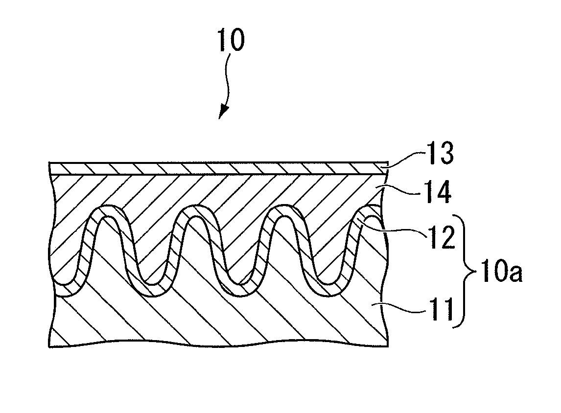
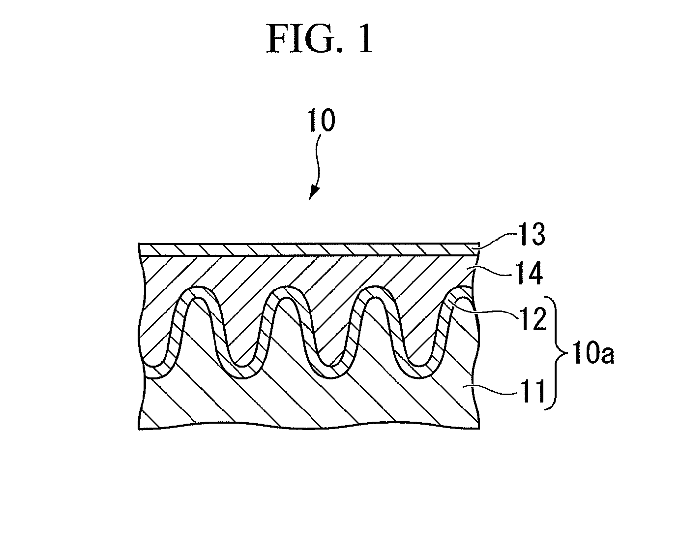
The capacitor manufacturing method of this embodiment has a step of preparing a capacitor substrate 10a by oxidizing the surface of the anode 11 to form the dielectric layer 12, a step of forming the solid electrolyte layer 14 on the surface of the dielectric layer 12 of the capacitor substrate 10a, and a step of forming the cathode 13 on the surface of the solid electrolyte layer 14.

In the step of preparing the capacitor substrate 10a, an example of the method used for electrolytically oxidizing the surface of the anode 11 is a method in which the surface of the anode 11 is oxidized within an electrolyte such as an aqueous solution of ammonium adipate by applying a voltage.

In the step of forming the solid electrolyte layer 14, a film-formation treatment that involves applying a conductive polymer solution to the dielectric layer 12 of the capacitor substrate 10a, and then drying the solut...

example 1

A capacitor substrate prepared in (4) above was subjected to 5 repetitions of the steps of dipping the substrate in the conductive polymer solution (I), gradually pulling the substrate up out of the solution, and then drying the substrate for 10 minutes using a 150° C. hot-air dryer, thereby forming a conductive polymer film (1) on the surface of the dielectric layer of the capacitor substrate (the first film formation).

Subsequently, the capacitor substrate with the conductive polymer film (1) formed thereon was subjected to two repetitions of the steps of dipping the capacitor substrate in the conductive polymer solution (V), gradually pulling the substrate up out of the solution, and then drying the substrate for 60 minutes using a 150° C. hot-air dryer, thereby forming a conductive polymer film (2) on the outside of the conductive polymer film (1) (the second film formation).

Following subsequent formation of a carbon film and a silver film on the outside of the conductive polymer...

example 2

With the exception of changing the conductive polymer solution (I) used in the first film formation in example 1 to the conductive polymer solution (II), a capacitor was prepared and evaluated in the same manner as that described for example 1. The results of the evaluations are shown in Table 1.


PUM


Abstract

A capacitor manufacturing method that enables a capacitor having a high withstand voltage, a high electrostatic capacitance and a satisfactorily small ESR to be manufactured simply and at a high level of productivity. In the capacitor manufacturing method, a film-formation treatment of applying a conductive polymer solution containing a π-conjugated conductive polymer, a polyanion and a solvent to the dielectric layer side of a capacitor substrate having a dielectric layer formed on the surface of an anode, and then performing drying to form a conductive polymer film, is performed at least twice, and the conductive polymer solution used in at least one film-formation treatment among the second film-formation treatment and subsequent film-formation treatments is a high-viscosity solution having a higher viscosity than the conductive polymer solution used in the first film-formation treatment.

Description

TECHNICAL FIELDThe present invention relates to a method for manufacturing a capacitor such as an aluminum electrolytic capacitor, a tantalum electrolytic capacitor or a niobium electrolytic capacitor.Priority is claimed on Japanese Patent Application No. 2008-257346, filed Oct. 2, 2008, the content of which is incorporated herein by reference.BACKGROUND ARTIn recent years, the digitalization of electronic equipment has been accompanied by a growing demand for reductions in the high-frequency region impedance (the equivalent series resistance) of the capacitors used in the electronic equipment. Conventionally, in order to satisfy these demands, so-called functional capacitors (hereinafter abbreviated to simply “capacitors”) that use an oxide film of a valve metal such as aluminum, tantalum or niobium as a dielectric body have been used.As disclosed in Patent Document 1, the structures of these capacitors generally include an anode composed of a porous body of a valve metal, a dielec...

Claims


Application Information

Patent Timeline
IPC IPC(8): B05D5/12B05D3/00
CPCH01G9/0036H01G9/028Y02E60/13H01G11/48H01G11/56H01G9/15
Inventor NING, TAILUFUJIKI, HIRONAOYOSHIDA, KAZUYOSHISHINGAI, MICHIKO
Owner SHIN-ETSU POLYMER CO LTD
Learn More