High capacity ion chromatography stationary phases and method of forming

a technology of ion chromatography and stationary phase, which is applied in the direction of chromatographic cation exchangers, ion exchangers, separation processes, etc., can solve the problems of increasing manufacturing time and labor, taking a substantial period of time, and optimizing the packed column, so as to achieve excellent bromate resolution and excellent bromide resolution , the effect of optimal selectivity

Active Publication Date: 2011-09-01
DIONEX CORP
View PDF16 Cites 17 Cited by
  • Summary
  • Abstract
  • Description
  • Claims
  • Application Information

AI Technical Summary

Benefits of technology

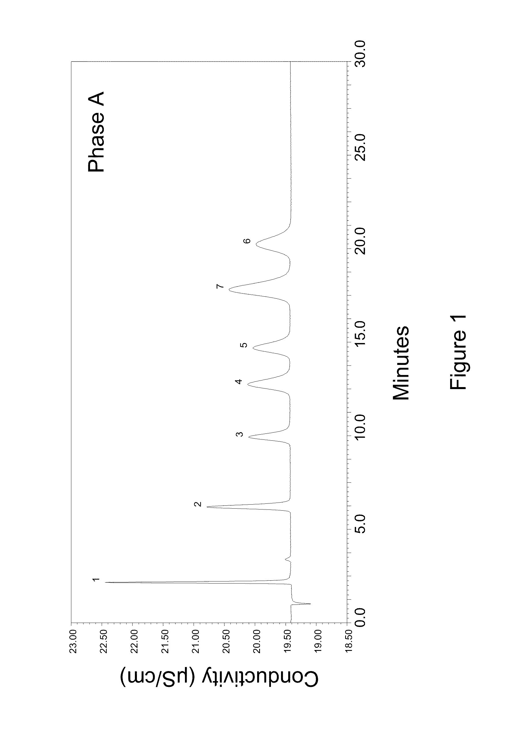
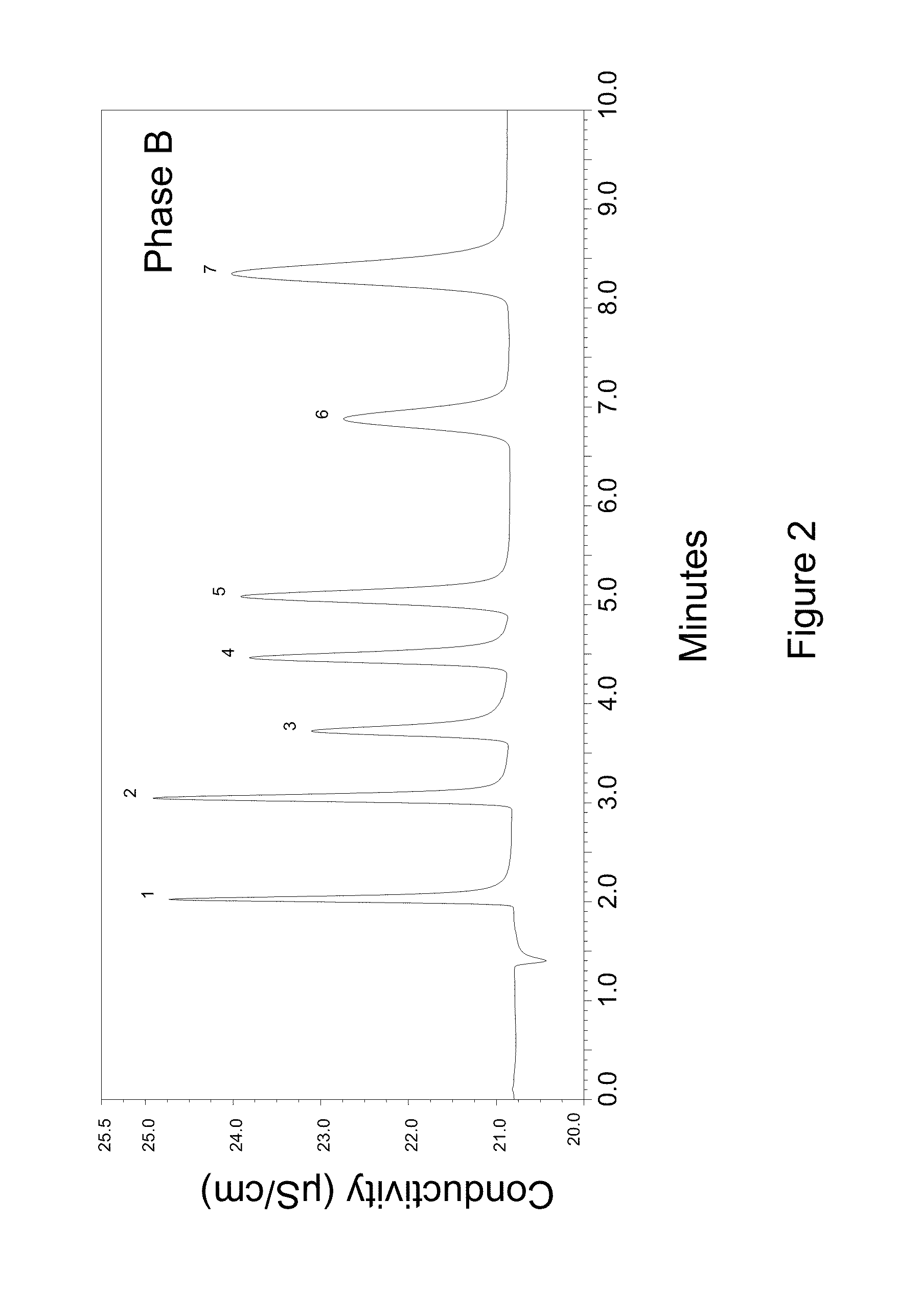
[0012]The present invention provides numerous advantages. For example hydrolytically stable ion exchange materials can be readily formed on a wide variety of substrates. Moreover, the hydrophilic nature of the condensation polymers formed over the first polymer layer are ideally suited for the separation of ions, providing excellent resolution of bromate from chloride as well as excellent resolution of both bromide and chlorate from nitrate. Condensation polymers can be formed from a wide variety of commercially available reagents to enable the preparation of materials of optimal selectivity for specific separation requirements. The first polymer layer and subsequent condensation polymer layers can be applied to a substrate after a column is packed with the substrate, facilitating rapid screening of suitable coating chemistries. Furthermore, coatings can also be applied to the substrate under slurry conditions or in packed beds in order to provide suitable synthesis scale for large-scale production, minimizing manufacturing cost. The coating process can be interrupted at any stage in the re...

Problems solved by technology

A disadvantage regarding the latex coating procedure is that it can take a substantial period of time, e.g., days or even weeks, to make an optimized packed column.
Such procedures typically require applying the coating after the column is packed which increases the manufacturing time and labor compared to synthetic methods which can provide a finished product prior to packing.
Also, latex synthesis is generally limited to water insoluble monomers, significantly limiting the choice of available mono...

Method used


Image

  • High capacity ion chromatography stationary phases and method of forming
  • High capacity ion chromatography stationary phases and method of forming
  • High capacity ion chromatography stationary phases and method of forming

Examples


example 1

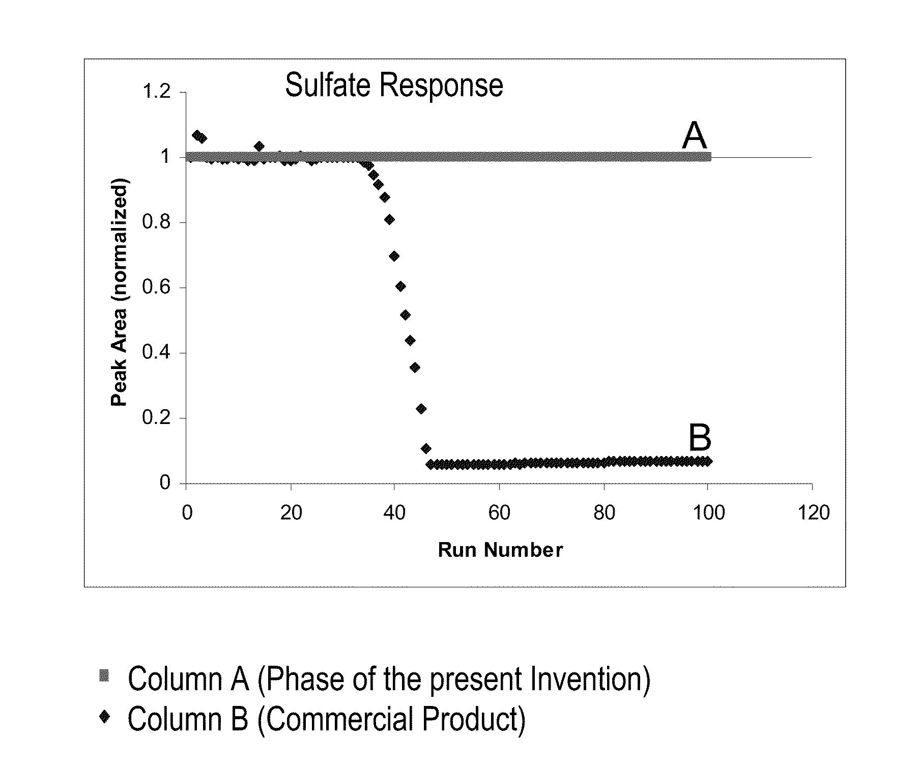
[0124]This example shows the synthesis of an organic layer on top of a chromatography substrate packing. Typically a polyvinyl benzene based polymer that is cross linked with divinyl benzene (55%) is used as the substrate resin. The process is as follows, 100 g of the substrate packing material was first dispersed in 50% IPA in Deionized (DI) water solution. The resin was submerged in the solution and mixed well. The resin was then rinsed twice with DI water and then filtered to a moist cake. The moist cake is dispersed in 200 g of DI water and then the monomer (A) and Initiator (B) was added. A) was comprised of a 10% to 20% monomer (Acrylic acid) in 200 gm of DI water and then 100 g of IPA solvent was added to the reaction mixture. The resin was mixed well. B) was comprised of 6 g of initiator (azobiscyanovaleric acid) which was added to a mixture of 30 g of DI water and 20 g of base (50% NaOH). The mixture was sonicated before adding this to the resin monomer mixture. The synthes...

example 2

[0125]For comparison purposes the substrate resin from Example 1 was also sulfonated. This procedure was designed to follow U.S. Pat. No. 7,291,395. The sulfonation procedure was as follows. A 1:5 ratio of resin to acetic acid (w / w) slurry was prepared first. Sulfuric acid was added to this mixture at a ratio of 1:20 (w / w) of resin to sulfuric acid. The mixture was stirred well and sulfonation proceeded at a) room temperature for 1 hour and at b) 4 hours at 50° C. The reaction was quenched by adding the resin mixture to a DI water reservoir of 1:10 resin mixture to DI water (w / w) ratio. The resin was filtered and washed with base and then with 20% methanol with a DI water rinse added in between these steps.

example 3

[0126]The resin from example 1 and 2 were next reacted following an amine epoxide chemistry as illustrated below. This was an in-column synthesis process and the resin was first packed into a 9×250 mm column by making a slurry in DI water and then packing this using DI water at a packing pressure of 4000 psi for 10 minutes. Next a chromatographic pump with a gradient proportioning valve was used for this work. The proportioning valve was connected to three solutions as listed below:

[0127]E1: 9.8% 1,4-Butanediol diglycidyl ether (BDDGE)

[0128]E2: 4.1% Methyl amine

[0129]E3: DI water

[0130]The solutions were proportioned as outlined below and pumped into the packed column from above (9×250 mm) and using a flow rate of 3 ml / min. The column was placed in a water bath at 60° C.

% E1% E2 % E3Comments72280Ground layer for 60 minutes10000Diepoxide layer for 35 minutes.0100 0 Methyl amine layer for 35 minutes———Repeat the diepoxide and amine layertwo more times.00100DI water rinse for 30 minutes...


PUM

PropertyMeasurementUnit
Timeaaaaaaaaaa
Flow rateaaaaaaaaaa
Electric chargeaaaaaaaaaa

Abstract

The present invention provides a new design for high capacity stationary phases for chromatography, for example, ion chromatography. The stationary phases include a first polymer layer in contact with and at least partially coating the substrate of the stationary phase. The first polymer layer serves as a foundation for the attachment, and in various embodiments, the growth and attachment, of a highly hyperbranched polymer structure, typically based on one or more products of condensation polymerization. Multiple components are of use in forming the first polymer layer and the hyperbranched polymer structure, thereby providing a stationary phase that can be engineered to have a desired property such as ion capacity, ion selectivity, and the like. Exemplary condensation polymers are formed by the reaction of at least one polyfunctional compound with at least one compound of complimentary reactivity, e.g., a nucleophilic polyfunctional compound reacting with an electrophilic compound.

Description

BACKGROUND OF THE INVENTION[0001]The present invention relates to a coated ion exchange material suitable for use in chromatography medium, and a method of forming this material.[0002]In one form of liquid chromatography, columns are packed with a discrete organic polymer granule or particle medium having functionally active surfaces. Materials for performing liquid chromatography are known where only thin outer surfaces of the chromatographic support materials are available for active exchange of ions with liquid media. For example, Small, et al. U.S. Pat. No. 4,101,460 describes an ion exchange composition comprising Component A, an insoluble synthetic resin substrate having ion-exchanging sites on its available surface, and Component B, a finely divided insoluble material, irreversibly attached thereto by electrostatic forces. Component B is typically deposited onto Component A from a latex.[0003]A disadvantage regarding the latex coating procedure is that it can take a substanti...

Claims


Application Information

Patent Timeline
IPC IPC(8): C08J5/20B01J41/12B01D15/08
CPCB01D15/36B01D15/361B01J47/00B01J41/04B01J41/20B01J39/26B01J39/17B01J39/19B01J41/13
Inventor SRINIVASAN, KANNANPOHL, CHRISTOPHER A.BHARDWAJ, SHEETALLIN, RONG
Owner DIONEX CORP
Why Eureka
Try Eureka