Detection of contaminating substances in an EUV lithography apparatus

a lithography apparatus and euv technology, applied in the field of detection of contaminating substances in the euv (extreme ultraviolet) lithography apparatus, can solve the problems of contaminating substances that cannot be detected, the ion current of the residual gas spectrum shown therein is not normalized, and the multi-layer mirror life is limited

Active Publication Date: 2011-09-01
CARL ZEISS SMT GMBH
View PDF12 Cites 5 Cited by
  • Summary
  • Abstract
  • Description
  • Claims
  • Application Information

AI Technical Summary

Benefits of technology

[0007]It is an object of the invention to provide an EUV lithography apparatus and also a method for detecting at least one contaminating substan

Problems solved by technology

Operation of the mirrors under vacuum conditions, typically at (total) pressures of between 10−9 mbar and 10−1 mbar, is necessary in such projection exposure apparatuses because the lifetime of the multilayer mirrors is limited by contaminating substances.
The ion current of the re

Method used


Image

  • Detection of contaminating substances in an EUV lithography apparatus
  • Detection of contaminating substances in an EUV lithography apparatus
  • Detection of contaminating substances in an EUV lithography apparatus

Examples


Embodiment Construction

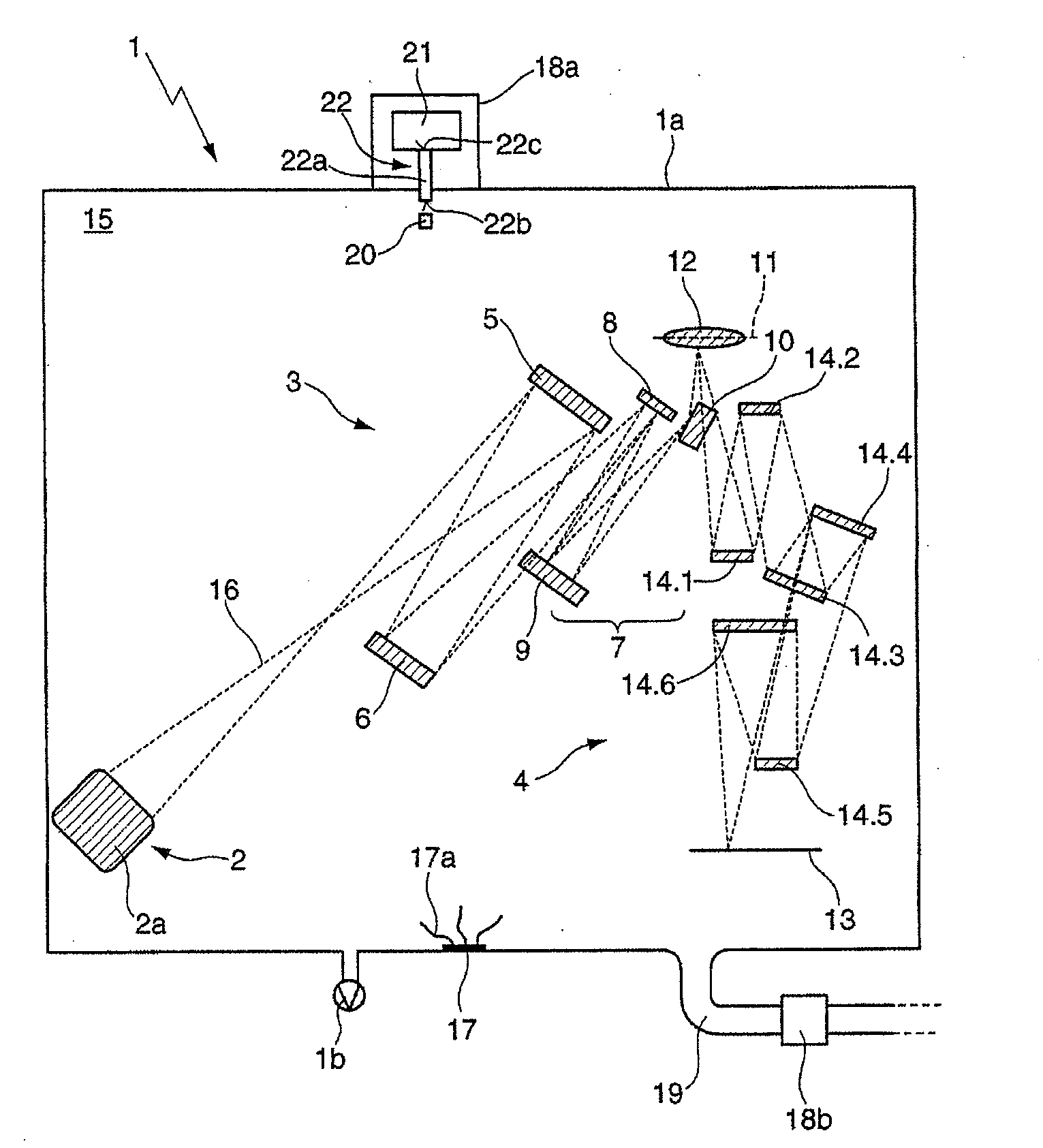
[0037]FIG. 1 shows a schematic illustration of an EUV lithography apparatus 1 having a housing 1a, to which a vacuum generating unit 1b (vacuum pump) is assigned. The housing 1a, in accordance with the optical function of the components arranged therein, is subdivided into three housing parts (not illustrated pictorially in FIG. 1), to be precise firstly into a first housing part having a light generating unit 2 comprising e.g. a plasma light source (not shown) and an EUV collector mirror 2a for focusing the illumination radiation.

[0038]Arranged in a second housing part adjacent thereto is the illumination system 3, which, following the beam course, has a mirror having field raster elements 5 and a mirror having pupil raster elements 6 as a light mixing device. A downstream group—acting as a telescope objective 7—of three mirrors, has a first and second mirror 8, 9, which are operated under normal incidence, and a third mirror 10, on which the light impinges under grazing incidence....


PUM


Abstract

An EUV (extreme ultraviolet) lithography apparatus (1) including: a housing (1a) enclosing an interior (15), at least one reflective optical element (5, 6, 8, 9, 10, 14.1 to 14.6) arranged in the interior (15), a vacuum generating unit (1b) generating a residual gas atmosphere in the interior (15), and a residual gas analyzer (18a, 18b) detecting at least one contaminating substance (17a) in the residual gas atmosphere. The residual gas analyzer (18a) has a storage device (21) having an ion trap for storing the contaminating substance (17a). Additionally, a method for detecting at least one contaminating substance by residual gas analysis of a residual gas atmosphere of an EUV lithography apparatus (1) having a housing (1a) having an interior (15), in which at least one reflective optical element (5, 6, 8, 9, 10, 14.1 to 14.6), is arranged, wherein the contaminating substance (17a) is stored in a storage device (21) in order to carry out the residual gas analysis.

Description

CROSS-REFERENCE TO RELATED PATENT APPLICATIONS[0001]This is a Continuation of International Application PCT / EP2009 / 004811, with an international filing date of Jul. 3, 2009, which was published under PCT Article 21(2) in English, which claims priority under 35 U.S.C. §119(a) to German Patent Application No. 10 2008 041 592.8, filed on Aug. 27, 2008, and the entire contents of which are hereby incorporated by reference; this application also claims the benefit under 35 U.S.C. §119(e)(1) of U.S. Provisional Application No. 61 / 092,251, filed on Aug. 27, 2008, the entire contents of which are also hereby incorporated by reference.FIELD OF AND BACKGROUND OF THE INVENTION[0002]The invention relates to an EUV (extreme ultraviolet) lithography apparatus, comprising: a housing enclosing an interior, at least one reflective optical element arranged in the interior, a vacuum generating unit for generating a residual gas atmosphere in the interior, and also a residual gas analyzer for detecting...

Claims


Application Information

Patent Timeline
IPC IPC(8): G03B27/52
CPCG03F7/7085G03F7/70983G03F7/70916G03F7/20H01J49/00
Inventor KRAUS, DIETEREHM, DIRK HEINRICHSCHMIDT, STEFAN-WOLFGANG
Owner CARL ZEISS SMT GMBH
Why Eureka
Try Eureka