
Electrodes incorporating nanostructured polymer films for electrochemical ion storage

a technology of nanostructured polymer films and electrochemical ions, applied in the field of electrochemical ion storage, can solve the problems of poor processability, low solubility of conductive polymers, and few large-scale applications of conductive polymers, and achieve the effect of improving the wetability of the substra

Inactive Publication Date: 2011-09-22
CALIFORNIA INST OF TECH +2
View PDF2 Cites 16 Cited by
  • Summary
  • Abstract
  • Description
  • Claims
  • Application Information

AI Technical Summary

Benefits of technology

The present invention is about electrode structures for storing ions using nanofibrillar films made from polymer nanofibers. The nanofibers are doped with a dopant and deposited on a substrate to form a film with a nanofibrillar morphology. The film has a high surface area and is substantially free from aggregates. The substrate can be made from a metal, conductive glass, carbon material, or a non-conductive material like paper. The nanofibers can be made using a variety of techniques such as insoluble hard templates, soluble soft templates, self-assembly external, nanowire seeding, and templateless processes. The nanofibers can also be doped with an anionic or cationic dopant. The invention also includes an electrochemical device incorporating the ion storage electrode and a method of forming the electrode on a substrate. The technical effects of the invention include improved ion storage capacity, reduced pore size, and increased surface area of the electrodes.

Problems solved by technology

Despite the promise presented by these materials, a number of challenges exist to their broad adoption and use in electrochemical devices.
One challenge is usually the low solubility of these polymers.
In addition, conductive polymers enjoy few large-scale applications due to their poor processability, the manufacturing costs associated with the material., material inconsistencies, toxicity, poor solubility in solvents, and inability to directly melt process.
In fact, the poor processability for many polymers requires the introduction of solubilizing substituents, which can further complicate their synthesis.
However, despite the promise offered by these conjugate polymer nanofibers, thus far no practical electrochemical devices have been developed using these materials.

Method used


Image

  • Electrodes incorporating nanostructured polymer films for electrochemical ion storage
  • Electrodes incorporating nanostructured polymer films for electrochemical ion storage
  • Electrodes incorporating nanostructured polymer films for electrochemical ion storage

Examples


example 1

Synthesis of Polymer Nanofiber Material

[0080]In one embodiment, polyaniline nanofibers were synthesized by initiator assisted oxidative rapid mixing polymerization for 24 to 48 hrs, and purified either by dialysis, or liquid / liquid extraction. (See, e.g., Tran, H. D., et al., Advanced Materials 2009, 21, (14-15), 1487-1499; and Li, D. et al., Accounts of Chemical Research 2008, 42, (1), 135-145, the disclosures of which are incorporated herein by reference.) The doping levels of these organic conductors are controlled by the extent of purification; the longer the dialysis, or the more number of washes employed, the more dedoped the polymer nanofibers become. A stable colloidal dispersion of nanofibers is obtained after purification for over a period of one week via repeated dialysis, or by using multiple washes during liquid / liquid extraction. This aqueous dispersion can then be used for coating a substrate such as copper, and aluminum.

example 2

Preparation of Electrode

[0081]A metal surface is cleaned in oxygen plasma, increasing hydrophilic character, and affording the correct surface energy for the spreading and deposition of a nanofiber film. Typically, a metal electrode is cleaned between 30 s to 2 min—note that it is susceptible to degradation from prolonged oxygen plasma (3 min). Aqueous dispersions of nanofibers of polyaniline are mixed with an oil such as a hydrocarbon of heavy (chloroform, carbon disulfide, chlorobenzene), or low (toluene, benzene, hexane) density. A film is produced at the liquid / liquid interface between a binary system of immiscible solvents. An electrode needs to be in contact with the liquid / liquid interface for deposition to occur, and needs to be wet with an aqueous layer prior to polymer deposition. This is achieved by immersion of an electrode in water after treatment with oxygen plasma, and before spreading of film occurs. A film growth solution contains polymer, water, and oil contained i...

example 3

Electrode Testing

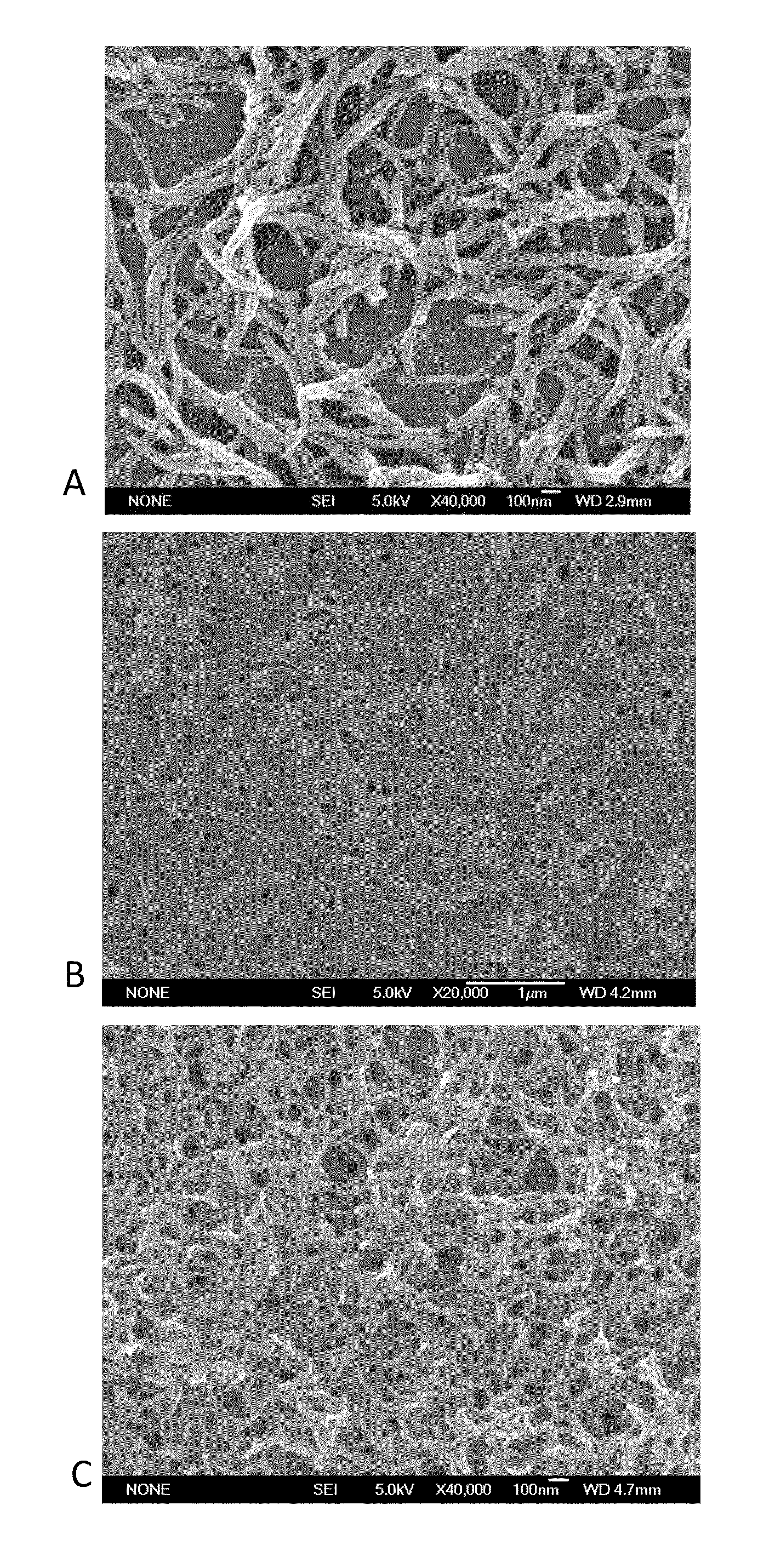
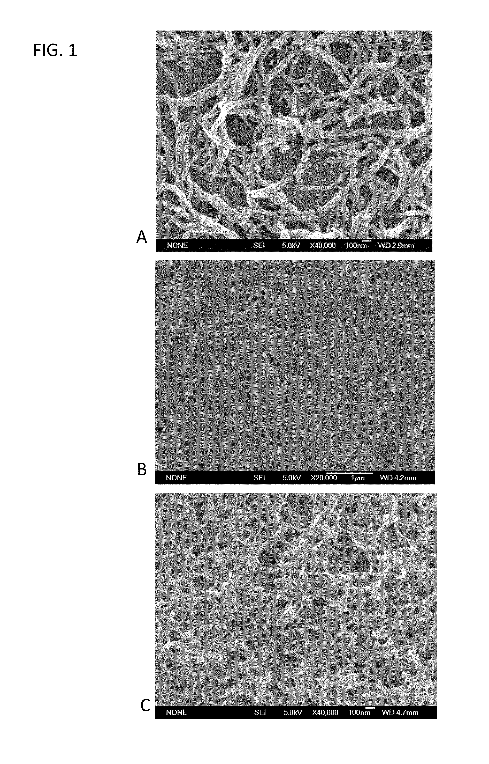
[0084]In one embodiment, electrodes (1.5 cm2) are punched from the nanopolyaniline (n-PANI) films on aluminum substrate provided by made in accordance with the processes set forth in Examples 1 and 2, above. In a glove box filled argon with argon, coin cells are assembled with the polymer film as the positive electrode in a lithium hall-cell. The electrolyte is 1 M LiPF6 in EC / DMC in accordance with the structure: (−)Li / 1 M LiPF6 in EC / DMC / PANT. SEM images of the undoped (FIG. 6A) and doped (FIG. 6B) electrodes made in accordance with this method show the nanofibrillar morphology of the conjugate polymers used.

[0085]The cells are then cycled at constant current between 2 V and 5.2 V for the anion intercalation (FIGS. 7A & 7B), and between 0.3 V and 3 V for the cation intercalation (FIGS. 8A & 8B). A rough estimate of the polyaniline electrodes capacity (considering a 200 nm thick film, 5% porosity and a density of about 1.2) gives 10 μAh for 1 ion intercalated per s...


PUM

PropertyMeasurementUnit
lengthaaaaaaaaaa
diameteraaaaaaaaaa
pore sizeaaaaaaaaaa

Abstract

Ion storage electrodes formed by coating an underlying substrate with a nanofibrillar film of structured conjugate polymer nanofibers and methods of forming such electrodes are described herein. The electrical properties of the electrodes may be customized by modifying the structure of the polymer nanofibers, the thickness of the nanofiber film, and the pore size of the nanofiber films.

Description

CROSS-REFERENCE TO RELATED APPLICATIONS[0001]The current application claims priority to U.S. Provisional. Application No. 61 / 286,101, filed, Dec. 14, 2009, the disclosure of which is incorporated herein by reference.FIELD OF THE INVENTION[0002]The present invention relates generally to electrode structures for electrochemical ion storage and methods of making such electrodes, and more specifically to electrodes that incorporate nanostructured conducting polymer films.BACKGROUND OF THE INVENTION[0003]Conductive polymers, or more precisely intrinsically conducting polymers (ICPs), are organic polymers that conduct electricity. Such compounds may have metallic conductivity or be semiconductors. The biggest advantage of conductive polymers is their processability. As conductive polymers are also plastics, they can combine the mechanical properties (flexibility, toughness, malleability, etc.) of plastics with high electrical conductivity. Moreover, the properties of these materials can b...

Claims


Application Information

Patent Timeline
Patent Type & Authority Applications(United States)
IPC IPC(8): H01M4/60H01G9/042H01G9/155H01G9/145H01G9/15B05D5/12B82Y30/00B82Y99/00
CPCH01M4/0402H01M4/137H01M4/1399H01M4/366H01M4/60H01G11/48H01M4/66H01M2004/022Y02E60/122Y02E60/13H01G11/24H01M4/602Y02E60/10
Inventor YAZAMI, RACHIDWEISS, CEDRIC M.KANER, RICHARDD'ARCY, JULIO
Owner CALIFORNIA INST OF TECH
Learn More