Eureka AIR delivers breakthrough ideas for toughest innovation challenges, trusted by R&D personnel around the world.

Separation membrane for fuel cell, and method for production thereof

Inactive Publication Date: 2011-10-06
TOKUYAMA CORP
View PDF5 Cites 33 Cited by
  • Summary
  • Abstract
  • Description
  • Claims
  • Application Information

AI Technical Summary

Benefits of technology

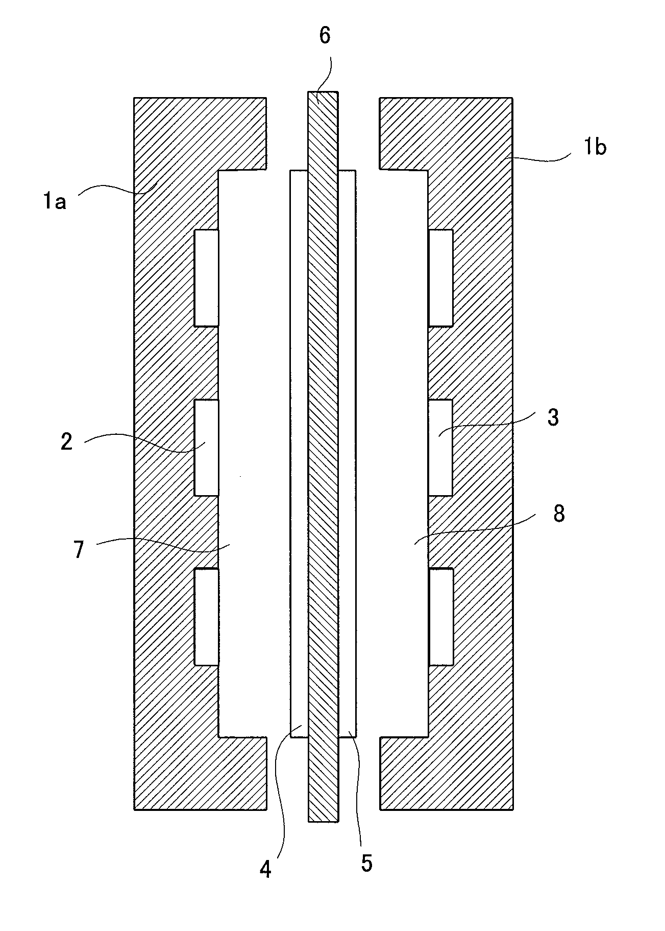
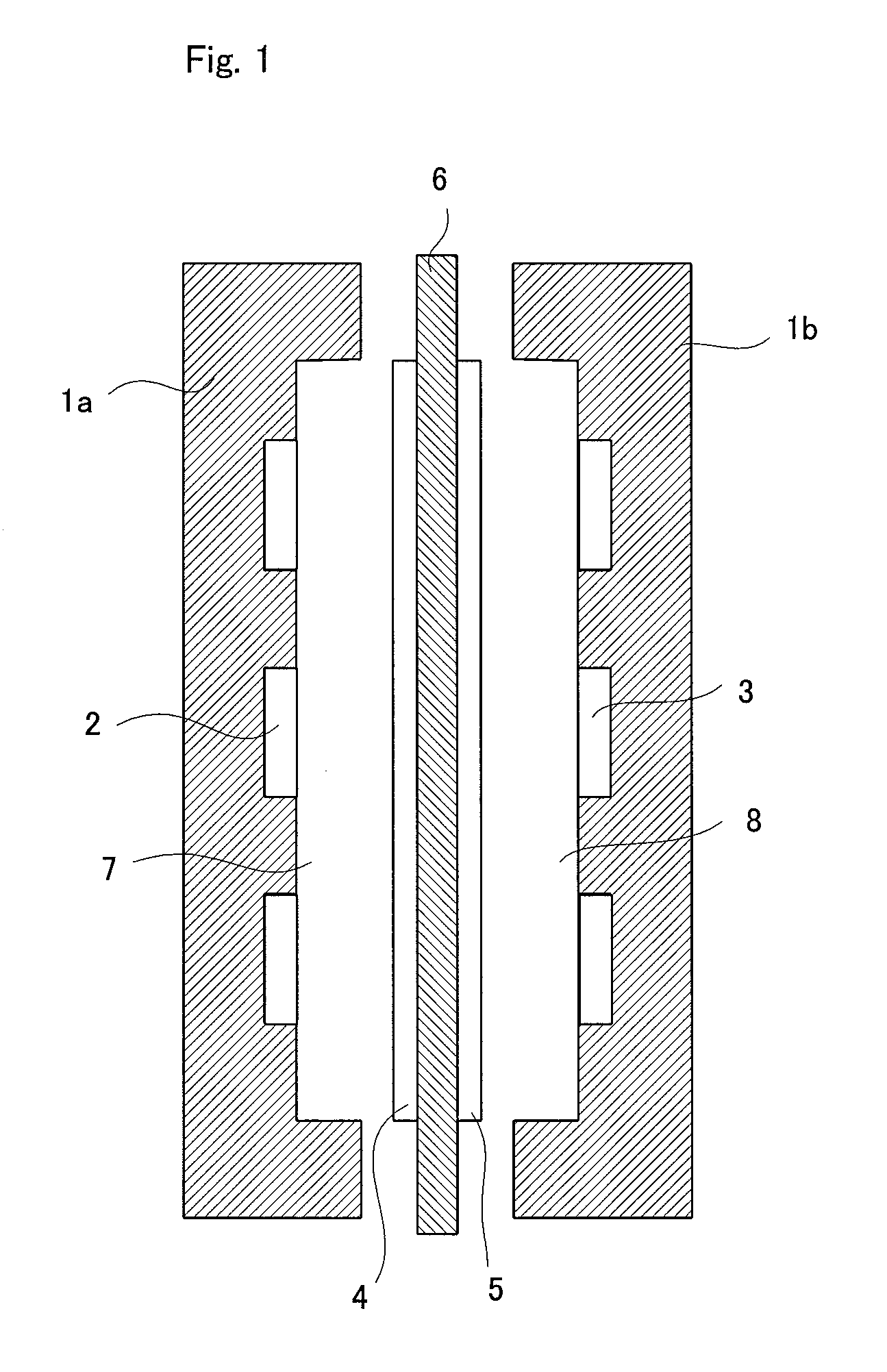
[0059]The membrane for fuel cell, of the present invention uses a cross-linked anion-exchange resin and is superior in dimensional stability, heat resistance and methanol non-permeability. In the membrane-catalyst electrode assembly for fuel cell, of the present invention, the catalyst electrode layers are bonded strongly to the membrane. Therefore, the membrane-catalyst electrode assembly for fuel cell has a small internal resistance and, when the membrane is used in a fuel cell, the fuel cell shows a high output voltage.
[0060]In the membrane for fuel cell, of the present invention, a polymer having a weakly acidic group is adhered to the surface of a polymer electrolyte membrane. The anion-exchange resin forming the polymer electrolyte membrane has a strongly basic anion-exchange group; therefore, the strongly basic anion-exchange group forms ion pair with the weakly acidic group of the polymer strongly and very efficiently; thereby, the polymer is fixed on the surface of the polymer electrolyte membrane at a high adhesion strength. This adhesion strength is high as compared with when the polymer has a strongly acidic ion-exchange group and the polymer electrolyte membrane has a strongly basic ion-exchange group.
[0061]Particularly when the polymer electrolyte membrane is a highly cross-linked anion-exchange resin and the polymer is a high-molecular (weight-average molecular weight=8,000 to 1,000,000) polymer having a weakly acidic group, the polymer hardly infiltrates into the ion-exchange resin. As a result, the polymer having a weakly acidic group can be adhered to the surface of the polymer electrolyte membrane in a large amount in a strongly fixed state in which the weakly acidic group forms ion pair with the strongly basic group of the polymer electrolyte membrane.
[0062]Therefore, the membrane-catalyst electrode assembly for fuel cell, produced using the polymer electrolyte membrane of the present invention has an extremely high bonding strength between the polymer electrolyte membrane and the catalyst electrode layers. When the present membrane-catalyst electrode assembly for fuel cell is used in a fuel cell and electricity is generated, the bondability between membrane and catalyst electrode layer is strikingly high; when electricity generation is conducted for a long period under severe conditions (e.g. high temperatures), the peeling of catalyst electrode layers takes place hardly and cell output is maintained stably.
[0063]In the membrane for fuel cell, of the present invention, ion pair is formed at a high efficiency between the anion-exchange group possessed by the anion-exchange resin constituting the polymer electrolyte membrane and the weakly acidic group possessed by the polymer having a weakly acidic group, and the polymer having a weakly acidic group is fixed strongly to the surface of the polymer electrolyte membrane. When the membrane for fuel cell, of the present invention is used in a fuel cell and electricity is generated, the polymer is in contact with a liquid fuel at the fuel chamber side or, at the oxidant chamber side, with the liquid fuel which crosses thereto over the membrane; however, the polymer hardly dissolves and diffuses in the liquid fuel which is in contact with the polymer. As a result, the migration of the polymer (dissolved in the liquid fuel) to the catalyst electrode layer and resulting poisoning / deactivation of the catalyst are suppressed greatly. Consequently, when the membrane is used in a direct liquid fuel cell, the cell can maintain a high output voltage for a long period.
[0064]As described above, the membrane for fuel cell, of the present invention can maintain the excellent characteristics of cross-linked type membrane for fuel cell and yet can reduce the internal resistance of membrane-catalyst electrode assembly for fuel cell, which has been a drawback of conventional membranes. Thus, the membrane for fuel cell, of the present invention is extremely useful in practical application of polymer electrolyte fuel cell.

Problems solved by technology

However, the fuel cell produced using the above-mentioned membrane-catalyst electrode assembly for fuel cell is unable to completely prevent occurring of the peeling between the polymer electrolyte membrane and the catalyst electrode layers when used for a long period.

Method used


Image

  • Separation membrane for fuel cell, and method for production thereof
  • Separation membrane for fuel cell, and method for production thereof

Examples


production example 1

[0213]As shown in Table 1, there was prepared a monomers composition comprising 100 mass parts of chloromethylstyrene, 3 mass parts (3.5 mol % of the total polymerizable monomers) of divinylbenzene, 5 mass parts of a polyethylene glycol diepoxide (molecular weight: 400) and 5 mass parts of tert-butyl peroxyethylhexanoate. In this monomers composition was immersed, at 25° C. for 10 minutes under atmospheric pressure, a porous membrane (thickness: 25 μm, porosity: 37%, average pore diameter: 0.03 μm) made of a polyethylene (PE, weight-average molecular weight: 250,000) to infiltrate the monomers composition into the porous membrane.

[0214]The porous membrane was taken out from the monomers composition and covered, at the both sides, with a polyester film (a peeling material) of 100 μm in thickness. Then, the covered porous membrane was heated at a nitrogen pressure of 0.3 MPa at 80° C. for 5 hours to polymerize the infiltrated monomers composition.

[0215]The membrane-shaped material obt...

production examples 2 to 3

[0217]Anion-exchange membranes were obtained in the same manner as in Production Example 1 except that the monomers composition and porous membrane of Production Example 1 were changed to those shown in Table 1. The anion-exchange membranes were measured for ion exchange capacity, water content, membrane resistance and membrane thickness. The results are shown in Table 2.

production example 4

[0218]100 mass parts of 4-vinylpyridine, 5 mass parts (3.9 mol % of the total polymerizable monomers) of divinylbenzene and 5 mass parts of tert-butyl peroxyethylhexanoate were mixed to prepare a monomers composition. In this monomers composition was immersed, at 25° C. for 10 minutes under atmospheric pressure, a porous membrane (thickness: 25 μm, porosity: 37%, average pore diameter: 0.03 μm) made of a polyethylene (PE, weight-average molecular weight: 250,000) to infiltrate the monomers composition into the porous membrane.

[0219]The porous membrane was taken out from the monomers composition and covered, at the both sides, with a polyester film (a peeling material) of 100 μm in thickness. Then, the covered porous membrane was heated at a nitrogen pressure of 0.3 MPa at 80° C. for 5 hours to polymerize the infiltrated monomers composition. The membrane-shaped material obtained was immersed in a 1:4 mixture of methyl iodide and methanol at 30° C. for 24 hours to obtain a quaternary...


PUM

PropertyMeasurementUnit
Temperatureaaaaaaaaaa
Percent by massaaaaaaaaaa
Fractionaaaaaaaaaa

Abstract

Disclosed is a membrane for a fuel cell, which comprises: a polymer electrolyte membrane which comprises a cross-linked anion-exchange resin having a strongly basic anion-exchange group such as a quaternary ammonium salt group, a quaternary pyridinium salt group and a quaternary imidazolium salt group; and a polymer which is attached on at least one surface of the polymer electrolyte membrane and has a weakly acidic group such as a polyacrylic acid. Also disclosed is a method for producing the membrane.

Description

TECHNICAL FIELD[0001]The present invention relates to a membrane for fuel cell, a method for producing thereof, and a membrane-catalyst electrode assembly for fuel cell. More particularly, the present invention relates to a polymer electrolyte membrane for fuel cell, comprising a cross-linked anion-exchange membrane, a method for producing thereof, and a membrane-catalyst electrode assembly for fuel cell.BACKGROUND ART[0002]Ion exchange resin membrane is in wide use as a membrane for cell (e.g. polymer electrolyte fuel cell, redox flow cell or zinc-bromine cell), a membrane for dialysis, etc. Polymer electrolyte fuel cell is used for an ion exchange membrane as the electrolyte. When a fuel and an oxidant are fed continuously into the polymer electrolyte fuel cell, they react with each other, generating a chemical energy. In the fuel cell, the chemical energy generated is taken out as an electric power, and the fuel cell is one of power generation system which is clean and highly eff...

Claims


Application Information

Patent Timeline
IPC IPC(8): H01M8/10
CPCH01M8/1004H01M8/1023Y02E60/523H01M8/1053H01M8/106H01M8/1025Y02E60/50Y02P70/50C08J5/18H01M8/02H01M8/10
Inventor WATAHIKI, YUKISADASUE, KAZUYUKIFUKUTA, KENJIYANAGI, HIROYUKI
Owner TOKUYAMA CORP
Why Eureka
Eureka Blog
Learn More