Process for production of direct reduced iron

a technology of direct reduction and reduction iron, which is applied in the direction of shaft furnaces, metal processing, furnaces, etc., can solve the problems of uneconomic step and unattractive process, and achieve the effect of improving the reduction properties of the reactor

Inactive Publication Date: 2011-10-13
LOUSSAVAARA KIIRUNAVAORA AB
View PDF0 Cites 27 Cited by
  • Summary
  • Abstract
  • Description
  • Claims
  • Application Information

AI Technical Summary

Benefits of technology

[0014]It is well known that in order to obtain a high strength reducing gas from a reformer in which the reactor off-gas is refined to syngas containing a high concentration of H2 and CO, it is desirable to maintain low level of steam in the inlet stream to the reformer. The basic reason for reduced steam content of the reducing gas is the diluent effect of the steam in the reforming operation. Though, removal of steam from the reformer would yield a high strength reducing gas, such a step is considered uneconomic because it would be necessary to cool the reformer effluent for water condensation and removal after which it would have to be reheated prior to introduction into the iron ore reduction facility. Cooling and reheating requires costly heat exchange equipment and associated large high temperature piping which would make the process unattractive. In addition, the water condensation step increases pressure drop and, thus, requires that the reformer operation be carried out at much higher pressure necessitating an increase in either the operating temperature or the steam-carbon ratio, or both, in order to meet the residual methane requirement. Current schemes for producing high strength reducing gas need to be improved for energy efficiency and reduced product cost. In order to improve this present invention employs a catalytic processing step arranged after the shaft furnace in which steam in the reactor off gas is shifted to hydrogen by unreacted carbon monoxide by the water shift gas reaction CO2+H2O=CO+H2. In the present described embodiment a catalyst such as magnetite or brown iron is used. The water shift gas reaction is sensible to temperature wherein the tendency to shift to reactants increases at higher temperatures. Hence, the relatively high temperatures in the reactor off gas which hereto has been considered as a problem can be used as an advantage. Also, the fact that reactor off-gas from the DRI reactor is of produced at low pressure which normally is considered as a drawback can be used as an advantage.

Problems solved by technology

Though, removal of steam from the reformer would yield a high strength reducing gas, such a step is considered uneconomic because it would be necessary to cool the reformer effluent for water condensation and removal after which it would have to be reheated prior to introduction into the iron ore reduction facility.
Cooling and reheating requires costly heat exchange equipment and associated large high temperature piping which would make the process unattractive.

Method used


Image

  • Process for production of direct reduced iron
  • Process for production of direct reduced iron

Examples


Embodiment Construction

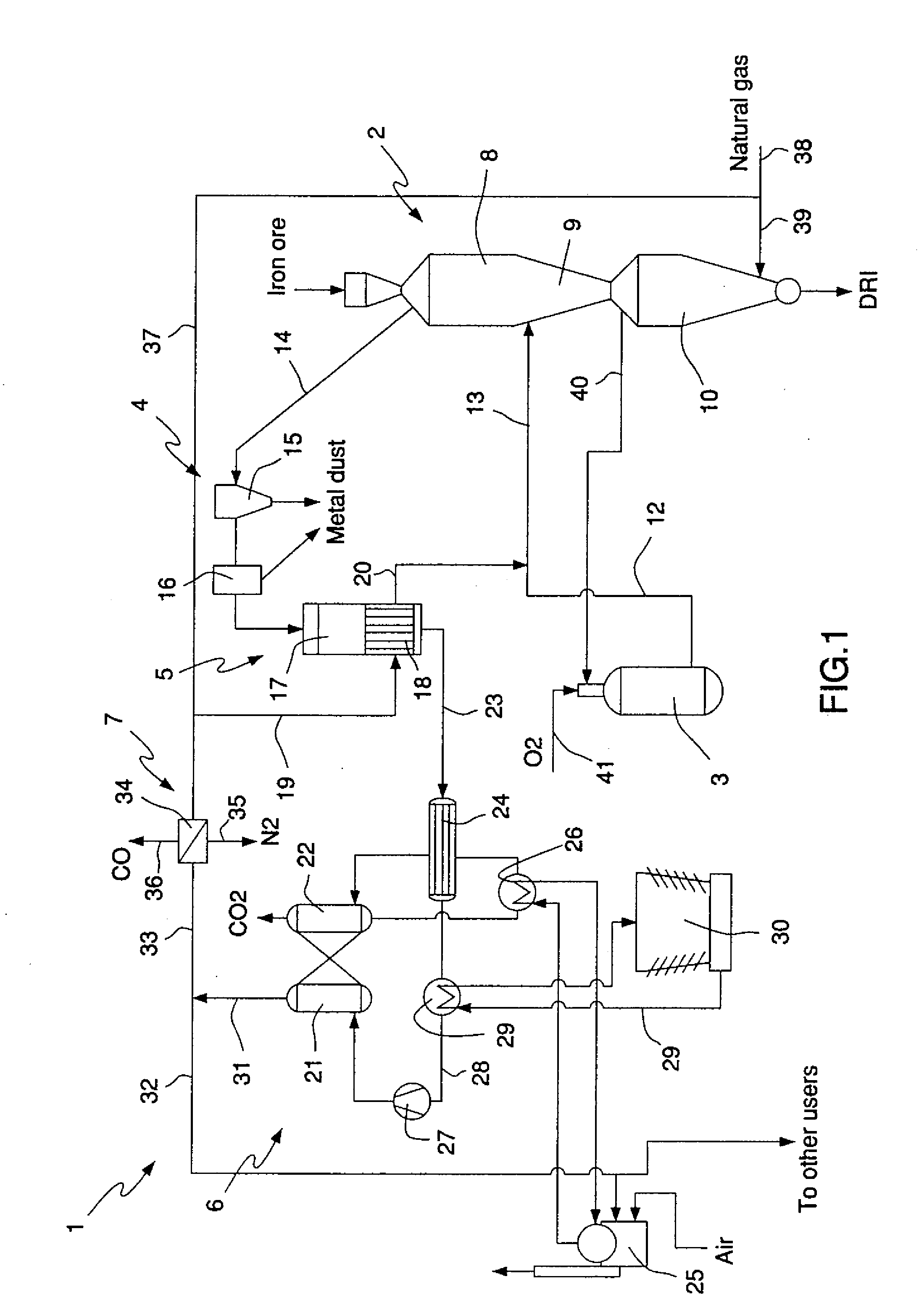
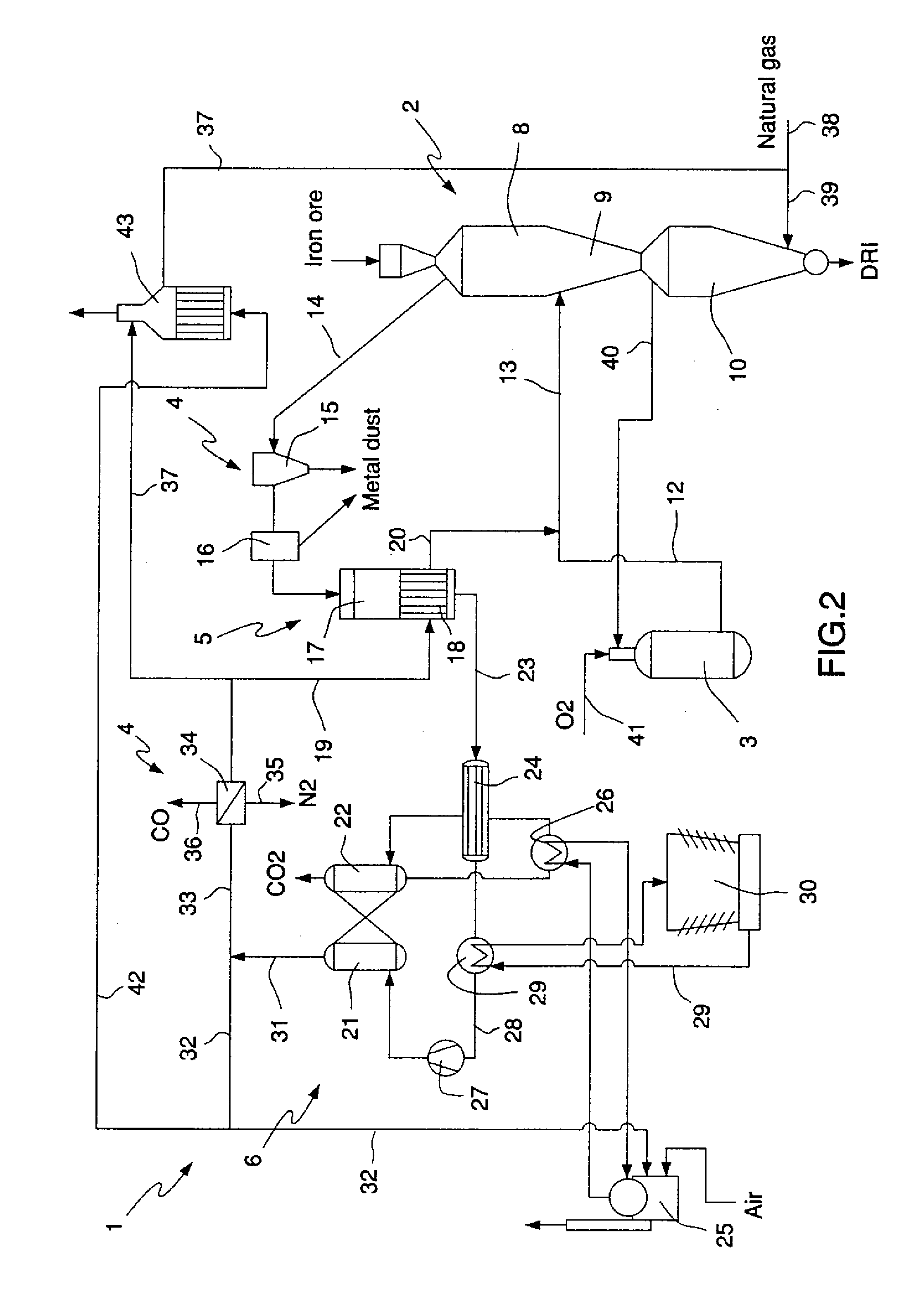
[0019]Two alternative process schemes are described here below, one with and one without a complementary heater for heating primary reformer effluent high in hydrogen H2. These schemes are shown in FIGS. 1 and 2, respectively.

[0020]With reference to FIG. 1 a first layout of a reduction plant designated by the reference numeral 1 suitable for performing the process according to the present invention is illustrated. In the layout numeral 2 generally represents a direct reduction shaft for production of DRI, 3 represents a gas generator supplying synthesis gas, otherwise known as syngas which is used gas recovered from the reactor and refined to be used as the reducing gas in the reduction shaft, 4 represents a particle cleaning system for separating metal dusting from reactor off gas drawn from the reactor, 5, 6 and 7 represent a reformation system comprising three reformation steps wherein 5 represents a first reformation step for steam reforming carbon monoxide present in the reacto...


PUM

PropertyMeasurementUnit
temperatureaaaaaaaaaa

Abstract

The present invention relates to a process for the direct reduction of iron ore performed by means of a plant comprising a gravitational furnace (2) having at least one iron ore reduction zone (8) in the upper part thereof, and at least one carbon deposition zone (9) and one reduced metal product cooling zone (10) in the lower part thereof, and means for feeding a reducing gas mixture into the reactor in correspondence to the with the reduction zone, means for recycle exhaust or reactor off gas from the reactor to syngas and mixing the recycled gas with natural gas to form a reducing gas mixture. According to the invention a in first reformation step (5) unreacted carbon monoxide CO and steam present in the reactor off gas is reformed to carbon dioxide and hydrogen following the water gas shift reaction CO+H20=CO2+H2, in a secondary reformation step the de-watered reactor off gas comprising mainly of carbon dioxide and hydrogen is processed to remove carbon dioxide, and in a third reformation step physical separation of both nitrogen and carbon oxide CO from the reducing syngas is carried out to bring down the levels of CO and any existing other gases in the recycled gas to as low level as possible such that recycled reducing gas is as close to pure hydrogen H2 as possible.

Description

FIELD OF THE INVENTION[0001]The present invention relates generally to a process for production of direct reduced iron according to the preamble of claim 1. More specifically, the present invention relates to a process for cleaning and removal of carbon dioxide and steam from spent reducing gas in a process for the direct reduction of iron.BACKGROUND OF THE INVENTION[0002]Direct reduction processes for producing metallized iron from iron oxide pellets, lump ores, or similar materials which include iron oxide, are widely known and used in the steel industry. Direct reduction (DR) processes produce metals from their ores by removing associated oxygen from the ores at temperatures below the melting temperature of any of the materials involved in the process. The product obtained as a result of a direct reduction process is known as DRI or “Direct Reduced Iron”. The direct reduction process converts iron ore into a highly metallized iron product. The actual reduction of the iron ore in ...

Claims


Application Information

Patent Timeline
Patent Type & Authority Applications(United States)
IPC IPC(8): C21B3/02
CPCB01D2257/504C21B13/0046C21B2100/04C21B13/02C21B2100/02C21B13/0073Y02P10/143Y02P10/122C21B2100/44C21B2100/66C21B2100/284C21B2100/24C21B2100/282C21B2100/26Y02P10/134C21B13/029
Inventor KNOP, KLAUSNGSTROM, STEN
Owner LOUSSAVAARA KIIRUNAVAORA AB
Why Eureka
Try Eureka