Microfluidic Embryo and Gamete Culture Systems

Inactive Publication Date: 2011-10-13
CRAIG H RANDALL
View PDF2 Cites 24 Cited by
  • Summary
  • Abstract
  • Description
  • Claims
  • Application Information

AI Technical Summary

Benefits of technology

[0060]Commercial in vitro fertilization laboratory procedures are largely characterized by sequential repetitive cell culture and micromanipulation steps currently performed by antiquated manual cell culture lab techniques. A relatively small number of standard lab manipulation and incubation steps performed in consistent sequential order makes In Vitro Fertilization (IVF) procedures especially amenable to automated mirofluidic cell culture, using standard and easily programmable laboratory algorithms. Microfluidic cell culture and cell transport techniques are potentially much more effective and efficient for IVF applications than currently used standard Petri dish and cell culture-in-test tube incubators. Current IVF lab procedures involve culturing simple tiny cells (embryos, oocytes, sperm) in relatively enormous cell culture media volumes in dishes or test tubes, whereas microfluidic systems incubate cells in small micro-chambers. Why store a Volkswagen in an aircraft hanger when an automobile garage is much more efficient and practical? The microfluidic systems are also very amenable to automated micro-manipulation of cells and embryos, and may easily benefit from microprocessor control.
[0063]Further, microfluidic systems can supply culture media and nutrients to gametes and developing embryos. They can sequentially change culture media to match embryo development stage, namely HTF for sperm and oocytes, pyruvate base for multi-cell embryos, intermediate for morula stage, glucose based for blastocyst, sodium depleted for oocyte freezing, etc. Such systems can sequentially concentrate or dilute cryopreservatives and media prior to freezing or after thawing oocytes, sperm, or embryos. They can supply fresh media by slow-flow to embryos during incubation and remove waste media from culture, including free radicals. Concentrations of dissolved gases in culture media (nitrogen, oxygen, carbon dioxide) can be tightly controlled, thus eliminating the need for culture fluid / gas atmosphere interface and associated prolonged equilibrium time. Such systems can automate and simplify sampling of culture media for chemical analysis. Finally, co-culture of oocytes and embryos with other cell types, including endometrial cells and tubal lining cells can be automated and miniaturized by including separate culture chambers with shared or transferred media and / or common culture chambers for simultaneous or sequential co-culture.
[0064]Finally, microfluidic systems can transport gametes and embryos between various culture chambers. Gametes or embryos can be moved between open or closed culture chambers. Gametes or embryos can be moved between open culture chambers using a multi-well, carousel or similar system. Open chambers can be supplied with slow flow media nutrients systems described above. Gametes and embryos can be moved between open chambers by a micropipette system. A combined open and close chamber system is very versatile and allows optimal culture conditions and micromanipulation procedures in a single combined system. A microfluidic system reduces or eliminates the risk of accidental dropping or loss of culture and embryos because manual movement of culture dishes or tubes between incubators or microscope stages is no longer necessary. Movement of embryos between micro-chambers for specialized functions and procedures can be simplified, or even automated, including: preparation (sperm capacitation, oocyte stripping, cryopreservative concentration and dilution); staging (holding cells between culture and procedure chambers); micromanipulation (temporary placement of oocytes / embryos for micromanipulation procedures including ICSI, blastomere biopsy, assist hatching, etc.); and catheter or freezing chamber loading or unloading.

Problems solved by technology

Separation of normal sperm from those with chromosomal and morphological abnormalities is difficult with current technology.
Currently used technology with relatively low efficiency for separation of sperm includes filtering sperm through a concentrated albumin solution, subjecting sperm to column chromatography, or layering sperm on a density gradient solution and applying high centrifugation forces.

Method used


Image

  • Microfluidic Embryo and Gamete Culture Systems
  • Microfluidic Embryo and Gamete Culture Systems
  • Microfluidic Embryo and Gamete Culture Systems

Examples


Embodiment Construction

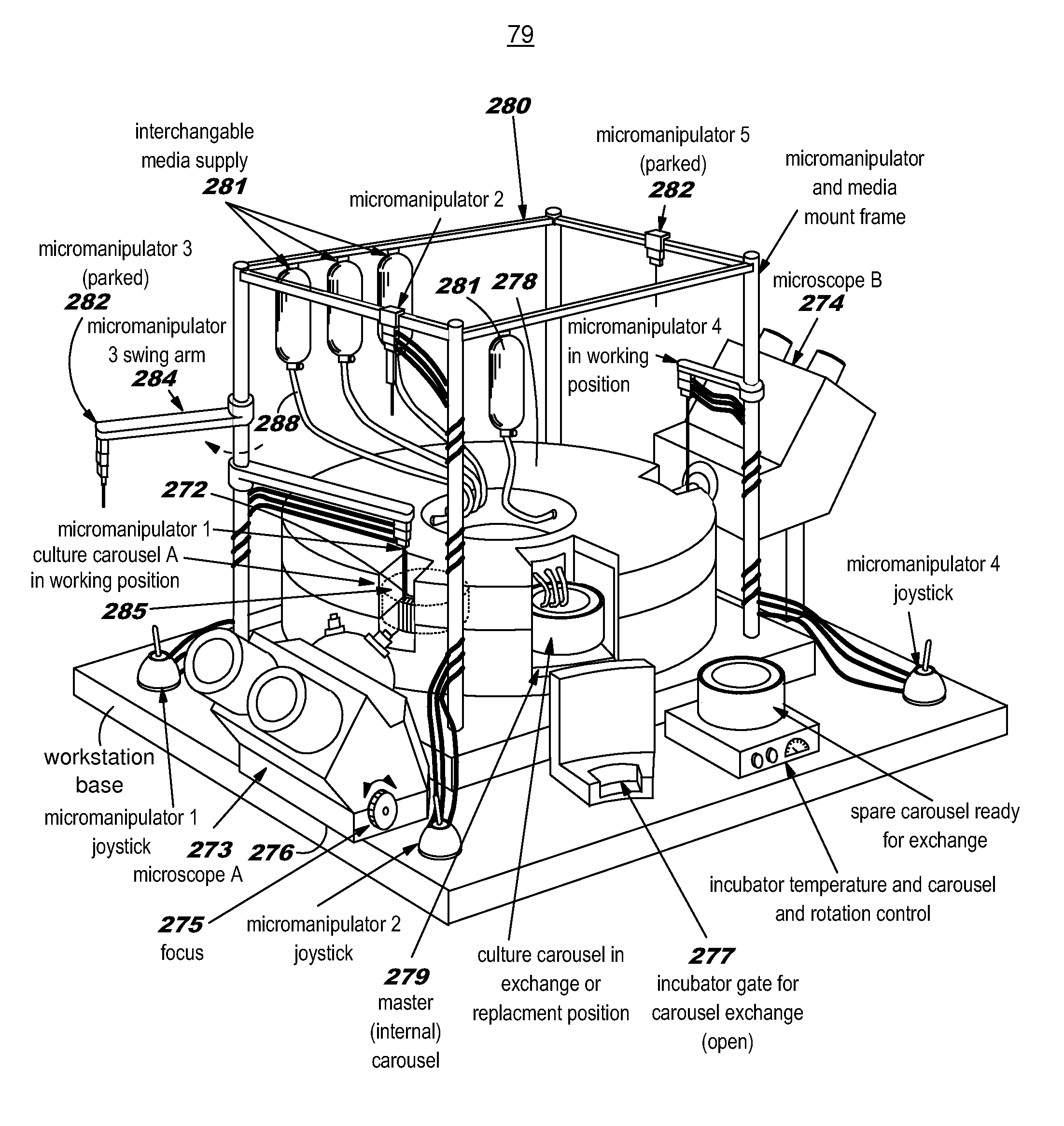
[0148]A more detailed description of components of a microfluidic IVF system is now provided.

[0149]The first component is a sperm separation system. The goal of the microfluidic sperm separation system is purification of sperm from semen and separation of normal sperm from those with chromosomal and morphological abnormalities is. If sufficient separation resolution is achieved by the system then simple inexpensive separation of X and Y chromosome sperm may be feasible, allowing sex determination of offspring in fertility patients and in commercial livestock.

[0150]A fractional distillation system permits exchange of sperm across laminar flow media streams along redundant parallel channels. Such a system may utilize either a passive gradient generator or an active gradient generator. The separation network is a “chicken-wire” configuration of adjacent, communicating laminar flow microchannels. Network gradient examples include albumin concentration gradients, chemotactic agents, pH g...


PUM


Abstract

A robotic microfluidic incubator system has a thin transparent sidewall and close proximity of the embryo / oocyte / cultured cells to the sidewall allow close approach of a side view microscope with adequate focal length for mid to high power. This arrangement permits microscopic examination of multiple culture wells when arranged in rows (linear or along the circumference of a carousel). Manual or automated side to side movement of the linear well row, or rotation of the carousel, allows rapid inspection of the contents each well. Automated systems with video capability also allow remote inspection of wells by video connection or Internet connection, and automated video systems can record oft-hours inspections or time lapse development in culture (i.e. embryo cell division progression, or axon growth in neuron cell cultures).

Description

CROSS REFERENCE TO RELATED APPLICATIONS[0001]This application claims the benefit of U.S. Provisional Application No. 61 / 113,581, filed Nov. 11, 2008, and U.S. Provisional Application No. 61 / 114,365, filed Nov. 12, 2008, each of which are incorporated herein by reference for all purposes.BACKGROUND OF THE INVENTION[0002]Classic cell culture consists of cells and tissues grown in Petri dishes containing large amounts of culture media and stored in large temperature and humidity controlled incubators. Microfluidic cell culture systems enclose cells and tissue specimens in tiny fluid-filled chambers and channels, reducing the scale of biologic culture systems in the same manner that integrated circuits reduced the scale of electronics from vacuum tubes and transistors.[0003]Significant advantages of microfluidic culture systems include small laboratory size, reduced laboratory expenditures, automated cell culture media changes and manipulations, and numerous labor saving innovations. Pu...

Claims


Application Information

Patent Timeline
IPC IPC(8): C12N5/02C12M3/00
CPCA01N1/02A61B17/43B01F5/061B01F7/00916B01F13/0059B01F13/0064B01F15/0404B01F2005/0636B01L3/502746B01L3/502753B01L3/50851B01L7/50B01L2300/0816B01L2300/088C12M21/06C12M23/08C12M23/10C12M23/16C12M29/26A61B17/435B01F25/431B01F25/431971B01F27/55B01F33/3017B01F33/30B01F35/81A01N1/0252A01N1/0284
Inventor CRAIG, H. RANDALL
Owner CRAIG H RANDALL
Why Eureka
Try Eureka