Material for organic electroluminescent element, and organic electroluminescent element

a technology of electroluminescent elements and materials, applied in thermoelectric devices, other domestic articles, organic chemistry, etc., can solve the problems of short life, device unsuitable for practical use on the other side, and inability to meet the practical application in some cases, and achieve long life and high efficiency.

Active Publication Date: 2011-12-29
IDEMITSU KOSAN CO LTD
View PDF4 Cites 40 Cited by
  • Summary
  • Abstract
  • Description
  • Claims
  • Application Information

AI Technical Summary

Benefits of technology

[0066]According to the present invention, a phosphorescent organic EL device having high efficiency and long lifetime can be provided by using the materials for organic electroluminescence device represented by formulae (A-1) to (A-5), (B-1) to (B-4), and (C-1) to (C-6) as a host material, particularly as a phosphorescent host.

Problems solved by technology
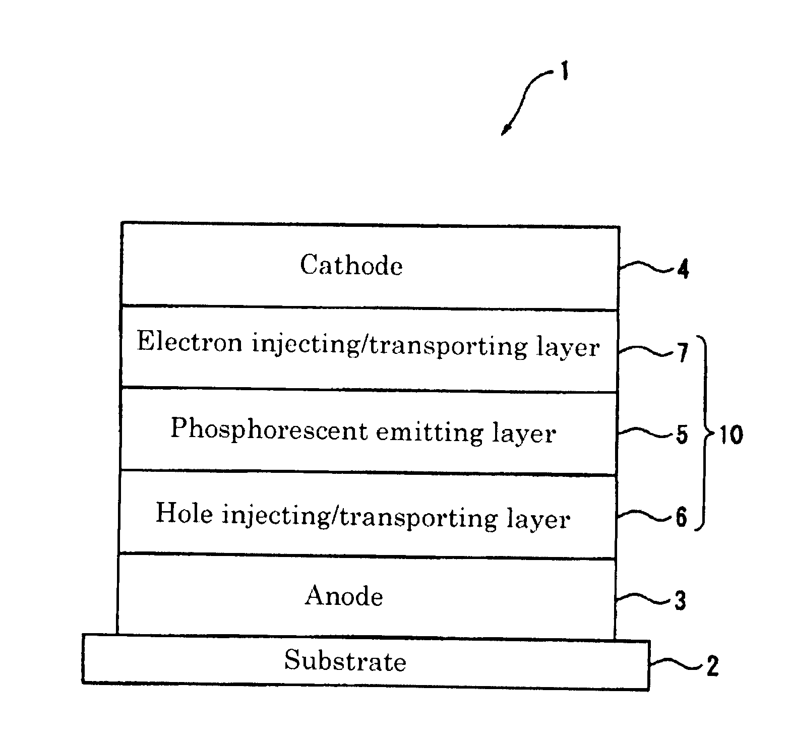
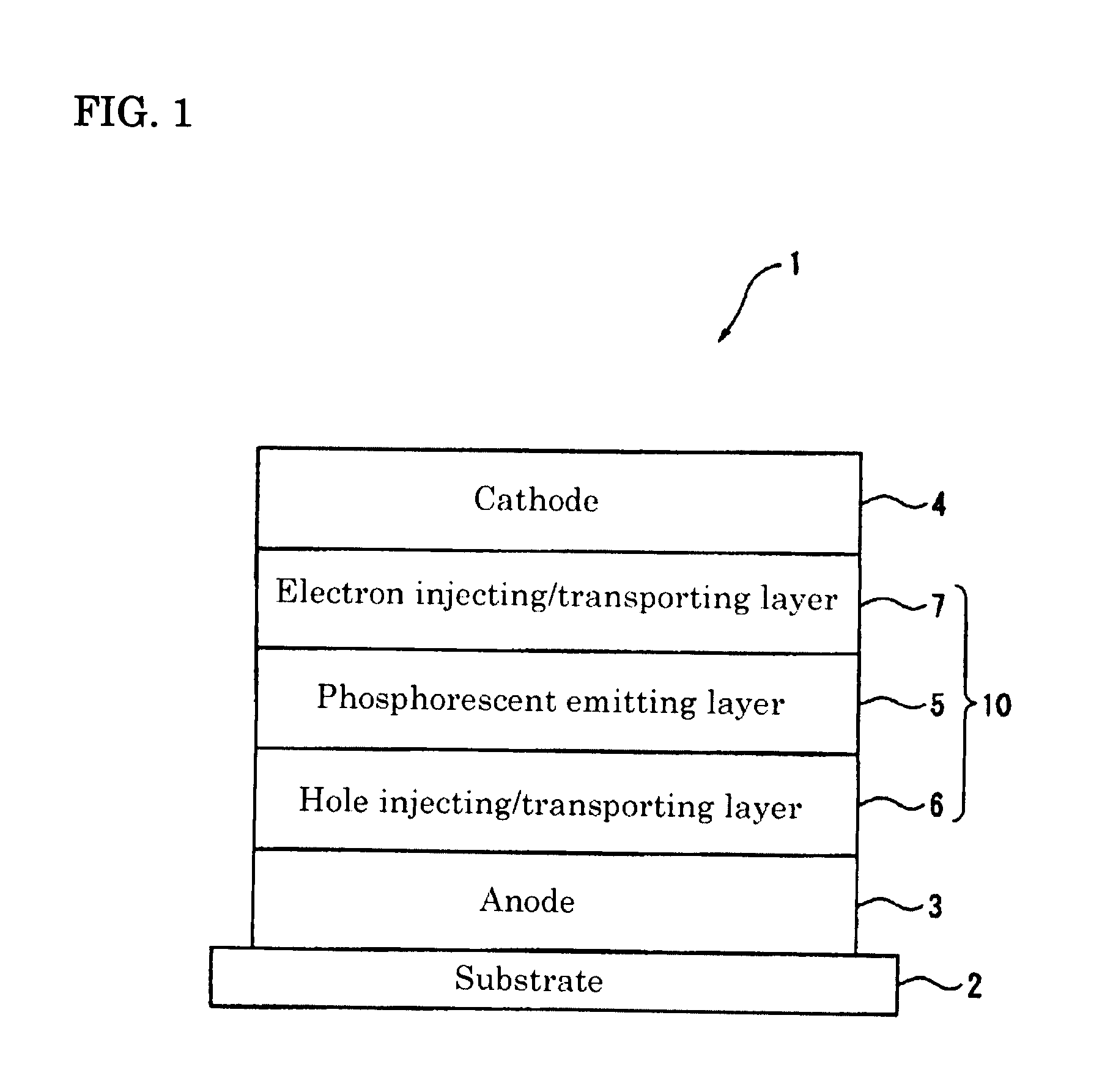
When CBP is used as a host material, the current efficiency is drastically enhanced by phosphorescent emission on one hand, but the lifetime is very short to make the device unsuitable for practical use on the other hand.
This technique enables the improvement of current efficiency and lifetime, but is not satisfactory for practical application in some cases.
Therefore, the fluorescent host cannot be simply used as a host material (phosphorescent host) for a phosphorescent layer.
Therefore, the energy transfer to a phosphorescent dopant having an emission wavelength in a visible light region of 500 to 720 nm can not be secured.
Further, the anthracene derivative cannot confine the excited triplet energy within a light emitting layer.
Therefore, the anthracene derivative is unsuitable as a phosphorescent host.
However, these documents are completely silent about the effectiveness of these compounds as a phosphorescent host.
However, the current efficiency and the device lifetime are not satisfactory even if these compounds are used as a phosphorescent host material.
However, these documents are completely silent about the effectiveness of an organic EL device employing these compounds in combination with a phosphorescent material.
In addition, a perylene ring and a pyrene ring, which are not suitable for use in a light emitting layer of phosphorescent device because of their low triplet energy level, are exemplified in these documents as the condensed polycyclic aromatic ring.
Namely, these documents fail to teach materials which are effective for a phosphorescent device.

Method used


Image

  • Material for organic electroluminescent element, and organic electroluminescent element
  • Material for organic electroluminescent element, and organic electroluminescent element
  • Material for organic electroluminescent element, and organic electroluminescent element

Examples


examples

[0314]The production of the materials of the invention will be described with reference to synthetic examples, but it should be noted that the present invention is not limited thereto.

Synthetic Reference Example 1-1

Synthesis of 2-bromo-9,9-dimethyl-7-(naphthalene-2-yl)-9H-fluorene

[0315]

[0316]In argon atmosphere, a mixture of 13.91 g (80.9 mmol) of 2-naphthaleneboronic acid, 30.0 g (80.9 mmol) of 2-bromo-7-iodo-9,9-dimethylfluorene, 4.67 g (4.0 mmol) of tetrakis(triphenylphosphine)palladium (0), 200 ml of toluene, 200 ml of dimethoxyethane, and 122.36 g of a 2 M sodium carbonate aqueous solution was refluxed under stirring for 8 h and left standing overnight. After adding water, the mixture was stirred at room temperature for one hour. After filtration and extraction with toluene, the organic phase was washed with water and then with a saturated saline solution. After drying over sodium sulfate, the toluene was distilled off under reduced pressure. The residue was purified by silica ...

synthetic example a-1

Synthesis of Compound 2-2

[0361]

[0362]In argon atmosphere, a mixture of 3.30 g (8.26 mmol) of 2-boromo-9,9-dimethyl-7-(naphthalene-2-yl)-9H-fluorene, 2.46 g (8.26 mmol) of 3-(phenanthrene-9-yl)phenylboronic acid, 0.38 g (0.33 mmol) of tetrakis(triphenylphosphine)palladium (0), 90 ml of toluene, 30 ml of dimethoxyethane, and 12.5 g of a 2 M sodium carbonate aqueous solution was stirred at 85° C. for 8 h. The reaction mixture was left cooled down to room temperature, added with water, stirred for one hour, and left standing overnight. Then, the reaction mixture was added with water and stirred at room temperature for one hour. After filtration, the filtrate was extracted with toluene. The organic phase was washed with water and then with a saturated saline solution and dried over sodium sulfate, and then toluene was removed by distillation under reduced pressure. The obtained oily substance was purified by silica gel chromatography to obtain 3.40 g (yield: 72%) of compound 2-2.

[0363]Ma...

synthetic example a-2

Synthesis of Compound 2-1

[0364]

[0365]Compound 2-1 was synthesized in the same manner as in the synthesis of compound 2-2 except for using 4-(phenanthrene-9-yl)phenylboronic acid in place of 3-(phenanthrene-9-yl)phenylboronic acid.

[0366]Mass spectrum analysis showed m / e=572 to the molecular weight of 572.25.


PUM

PropertyMeasurementUnit
triplet energyaaaaaaaaaa
wavelengthaaaaaaaaaa

Abstract

An organic electroluminescence device and a material for producing the organic electroluminescence device. The organic electroluminescence device includes an organic thin film layer between a cathode and an anode, the organic thin film layer including one or more layers, in which the organic thin film layer includes one or more light emitting layers and at least one of the light emitting layers includes a phosphorescent material and a host material. The host material has an essential structure in which a naphthalene ring is bonded to a fluorene skeleton, dibenzofuran skeleton, or dibenzothiophene skeleton. The organic electroluminescence device is a phosphorescent device having high efficiency and long lifetime.

Description

TECHNICAL FIELD[0001]The present invention relates to an organic electroluminescence device (hereinafter referred to as “organic EL device”) and a material for organic electroluminescence device. In particular, it relates to an organic electroluminescence device having a green-emitting layer and a material for use in the production of such an organic electroluminescence device.BACKGROUND ART[0002]An organic EL device, which has an organic thin film layer including a light emitting layer between an anode and a cathode and which emits light from an exciton energy resulted from the recombination of holes and electrons injected into the light emitting layer, has been known.[0003]Sine the organic EL device is a spontaneous emitting device, it has been expected to be applicable, using its advantages, to a light emitting device with high current efficiency, high image quality, low power consumption and wide design freedom for thinner products. The organic EL device has been still required ...

Claims


Application Information

Patent Timeline
Patent Type & Authority Applications(United States)
IPC IPC(8): H01L51/54C07C255/51C07C13/547C07C13/66C07C13/60C07D307/91C07F7/08
CPCC09K11/06C09K2211/1029C09K2211/1059C09K2211/185H05B33/14H05B33/20C07D307/91Y10S428/917H10K85/623H10K85/622H10K85/633H10K85/321H10K85/631H10K85/615H10K85/346H10K85/657H10K85/342H10K50/11H10K2101/10H10K50/00
Inventor TAKASHIMA, YORIYUKIIWAKUMA, TOSHIHIROOGIWARA, TOSHINARIHOSOKAWA, CHISHIOITO, MITSUNORI
Owner IDEMITSU KOSAN CO LTD
Why Eureka
Try Eureka