Steam driven direct contact steam generation

Inactive Publication Date: 2012-01-05
EX TAR TECH
View PDF1 Cites 47 Cited by
  • Summary
  • Abstract
  • Description
  • Claims
  • Application Information

AI Technical Summary

Benefits of technology

[0023]Steam injection is currently the only method commercially used on a large scale for recovering oil from deep (non-minable) oil sands formations. Sometimes additional solvents are used, mainly hydrocarbons. There are a few disadvantages to the existing steam generation methods. For example, the steam is much cleaner than is needed for injection. To achieve the water quality currently used for steam injection, the water is extensively treated—the first stage is to separate the oil and de-oiling. To achieve that, the produced water is cooled to a temperature at which it can efficiently be de-oiled to the water treatment plant feed specifications where it is treated to the boiler feed water specifications. The need to cool the water decreases the SAGD's overall efficiency. In recent year there has been a

Problems solved by technology

There are a few disadvantages to the existing steam generation method

Method used


Image

  • Steam driven direct contact steam generation
  • Steam driven direct contact steam generation
  • Steam driven direct contact steam generation

Examples


example 2

[0154]The graph in FIG. 23 simulates the process as described in FIG. 2A. The driving steam 9 temperature was constant at 450° C. The liquid water 7 was at temperature of 25° C. and had a constant flow of 1000 kg / hour. The produced steam product 8 was saturated. The graph shows the amount of drive steam 9 required to transfer the liquid water 7 into the gas phase as a function of the pressure of the driving steam 9. When the system pressure was 2 bar, 3.87 tons / hour of driving steam was needed to convert the water to saturated steam at temperature of 121° C. For a 50 bar system pressure, 5.14 tons / hour of driving steam was used to generate saturated steam at 256° C. The simulation results are summarized in the following table:

Temperature DrivingSystem of SaturatedSteam PressureproducedFlow(bar)Steam(kg / hr)100.00311.825127.9475.00291.355161.7850.00264.745135.6625.00224.704914.4620.00 213.114821.4215.00198.984696.4110.00180.534515.835.00152.404218.443.00134.034018.9922.00120.683870.57...

example 3

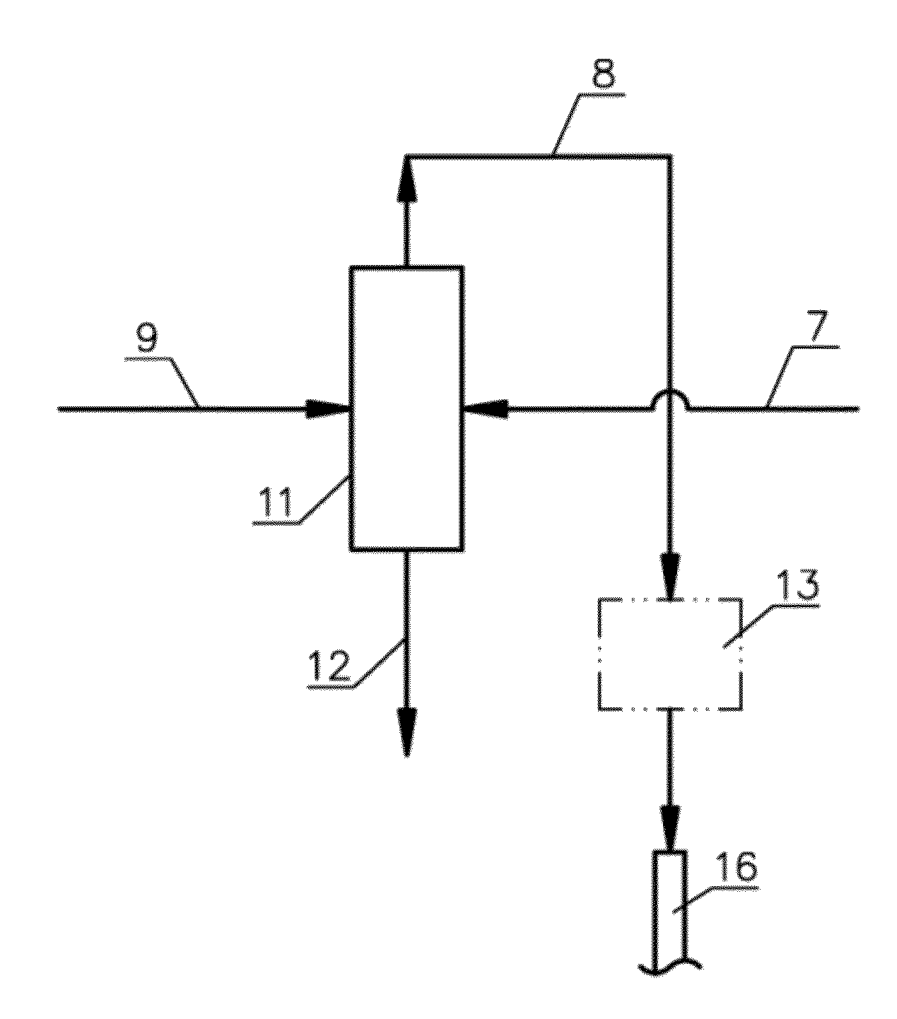
[0155]The graph in FIG. 24 simulates the process as described in FIG. 2A where the water feed includes solids and naphtha. As the pressure increases, the saturated temperature of the steam also increases from around 100 C at 1 bar to around 312 C 100 bar. Thus, the amount of superheated steam input at 450 C also increases from around 2300 kg / hr to 4055 kg / hr. The graph in FIG. 24 represents the superheated driving steam input 9 and the total flow rate (including hydrocarbons) of the produced gas 8.

Flow Number79128T, C25.00450.00120.61120.61P, atm2.002.002.002.00Vapor Fraction0.001.000.001.00Enthalpy, MJ−14885.08−29133.36−6692.49−37325.62Total Flow, kg / hr1000.002311.54414.732896.81Water600.002311.54114.202797.34Solids300.000.00300.004.14E−17Naptha100.000.000.5399.47

example 4

[0156]The following table simulates the process as described in FIG. 3 for insitue oilsands thermal extraction facilities, like SAGD, for two different pressures. The water feed is hot produced water at 200 C that includes solids and bitumen. The heat source Q′ for the simulation was 12 KW.

[0157]For a system pressure of 400 psi the total Inflow of water, solids and bitumen of flow 34 was 23.4 kg. 77% of the steam 31 is recycled as the driving steam 32 while 23% is discharged out of system at 283 C steam and hydrocarbons.

[0158]For a system pressure of 600 psi, the total Inflow of water, solids, and Bitumen of flow 34 was 22.5 kg. 80% of the steam 31 is recycled as the driving steam 32 while 20% is discharged out of system at 283 C steam and hydrocarbons.

Flow Number343531323633T, C.200243.42243.42243.43486.73243.43Press., psig400400400400400.00400.00Vapor Fraction00.001.001.001.001.00Enthalpy, kW−96.591−5.06−346.24−266.80−254.78−79.69Total Flow, kg / hr23.41.1796.8974.6674.6622.30Water,...


PUM


Abstract

The present invention is a system and method for steam production for oil production. The method includes generating steam, mixing the steam with water containing solids and organics, separating solids, and injecting the steam through an injection well or using it above ground for oil recovery, such as for generating hot process water. The system includes a steam drive direct contact steam generator. The water feed of the present invention can be hot produced water separated from a produced oil emulsion and/or low quality water salvaged from industrial plants, such as refineries and tailings from an oilsands mine.

Description

RELATED U.S. APPLICATIONS[0001]The present application is a continuation-in-part application under 35 U.S. Code Section 120 of U.S. application Ser. No. 12 / 635,597, filed on Dec. 10, 2009, and entitled “STEAM GENERATION PROCESS FOR ENHANCED OIL RECOVERY”, presently pending. The present application also claims continuation-in-part priority from U.S. patent application Ser. No. 12 / 636,729, filed on Dec. 12, 2009 and entitled “SYSTEM AND METHOD FOR MINIMIZING THE NEGATIVE ENVIROMENTAL IMPACT OF THE OILSANDS INDUSTRY”.STATEMENT REGARDING FEDERALLY SPONSORED RESEARCH OR DEVELOPMENT[0002]Not applicable.REFERENCE TO MICROFICHE APPENDIX[0003]Not applicable.BACKGROUND OF THE INVENTION[0004]1. Field of the Invention[0005]This application relates to a system and method for producing steam from a contaminated water feed for Enhanced Oil Recovery (EOR). This invention relates to processes for directly using steam energy, preferably superheated dry steam, for generating additional steam from cont...

Claims


Application Information

Patent Timeline
IPC IPC(8): E21B43/24F22B33/00C10G1/04
CPCB01D1/14B03D1/02B03D1/24E21B43/40E21B43/24E21B43/241B03D2203/006E21B43/35
Inventor BETZER TSILEVICH, MAOZ
Owner EX TAR TECH
Why Eureka
Try Eureka