

Method of Fabricating Thin Film by Microplasma Processing and Apparatus for Same
- Summary
- Abstract
- Description
- Claims
- Application Information
AI Technical Summary
Benefits of technology
Problems solved by technology
Method used
Image

Examples
Embodiment Construction
[0088]Embodiments of the present invention are now explained in detail with reference to the attached drawings. The following embodiments are merely for facilitating the understanding of this invention, and the present invention shall in no way be limited thereby. In other words, various modifications and other embodiments based on the technical spirit of the present invention shall be included in this invention as a matter of course.
(Explanation of Atmospheric-Pressure Plasma Thin-Film Fabrication Apparatus)
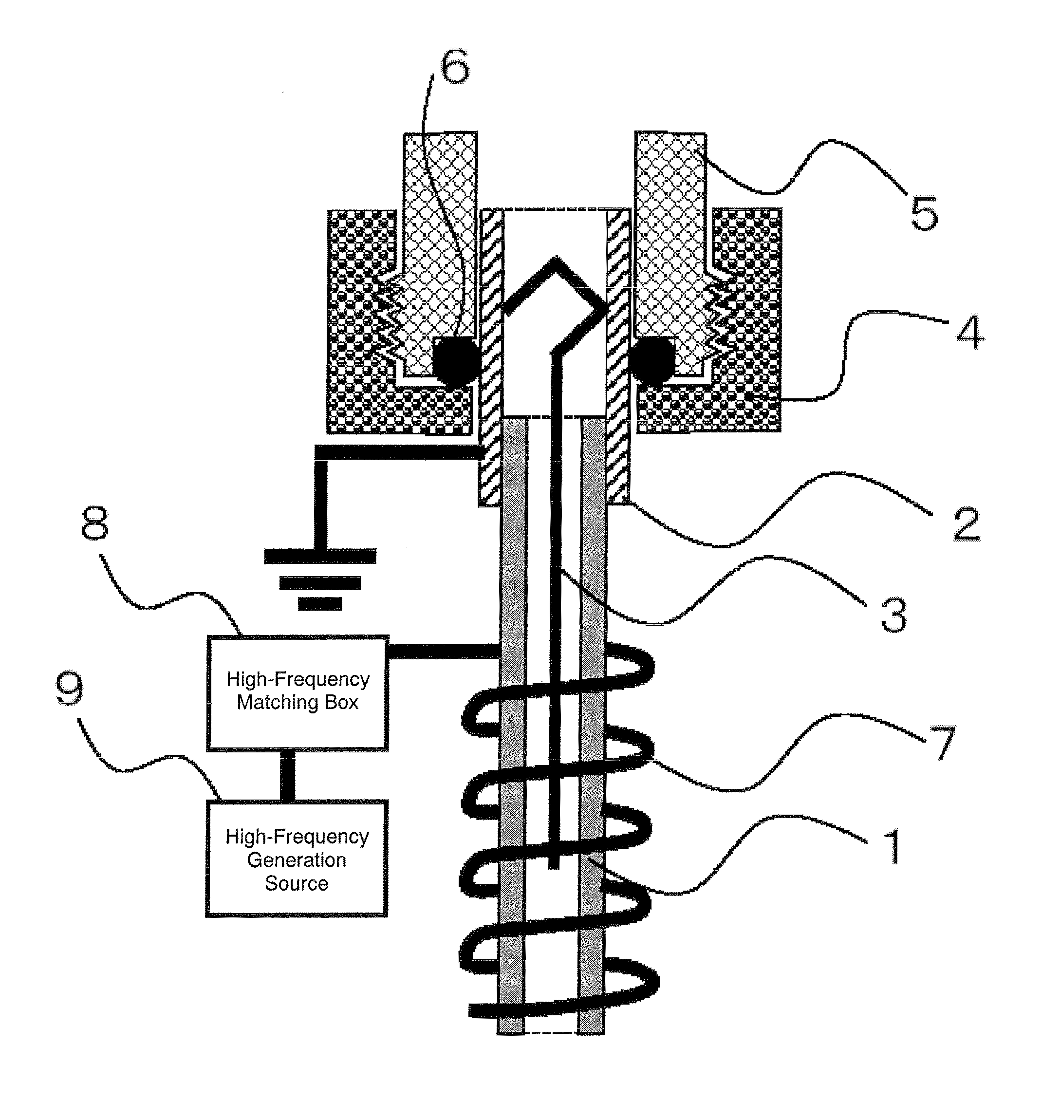
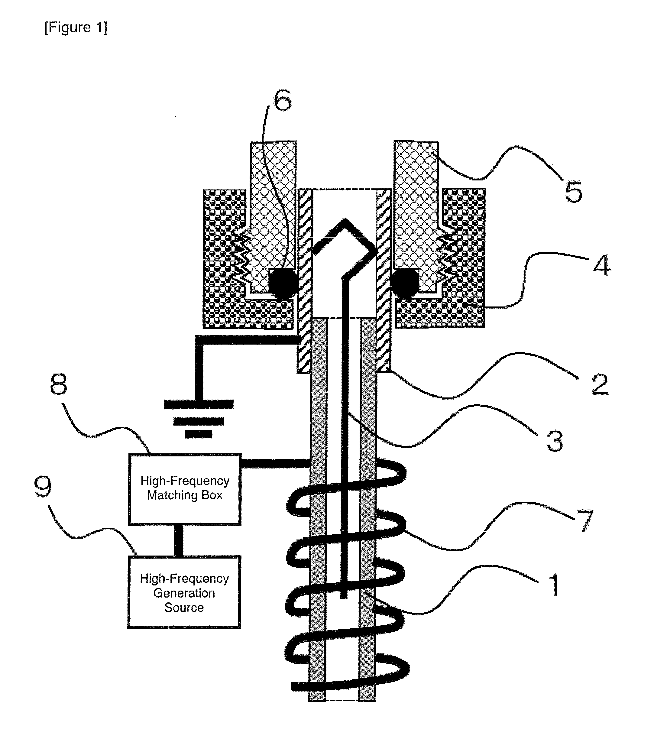
[0089]FIG. 1 is a view showing a frame format of the configuration of the plasma generator pertaining to the present embodiment and the connection method to the gas pipe. The plasma generator is configured from an alumina narrow tube 1, and a metal tube 2 for supporting the alumina narrow tube. The end of a raw material wire 3 inserted into the narrow tube is fixed to the inner wall of the metal tube 2 for supporting the narrow tube. The plasma generator is connected to a gas fe...
PUM
| Property | Measurement | Unit |
|---|---|---|
| Temperature | aaaaa | aaaaa |
| Thickness | aaaaa | aaaaa |
| Pressure | aaaaa | aaaaa |
Abstract
Description
Claims
Application Information