Water treatment plant for combined biomass and biogas production

a biogas and water treatment plant technology, applied in water/sludge/sewage treatment, filtration separation, moving filter element filters, etc., can solve the problems of large water outlet affected by man, high cost and waste of sewage, and substantially degrade the biological content of sewage, so as to achieve easy harvesting/collecting

Inactive Publication Date: 2012-02-02
CLEAR WATER ENERGY NORDIC
View PDF10 Cites 33 Cited by
  • Summary
  • Abstract
  • Description
  • Claims
  • Application Information

AI Technical Summary

Benefits of technology

[0026]Another object is to provide a method in which the alga e.g. macroalgae, may be easily harvested / collected on the water surface.
[0030]High flexibility for construction on site, resulting in low construction costs.

Problems solved by technology

Large outlets of water affected by man are a major problem around the world.
Cleaning wastewater, and in particular sewage is related to high costs and a high amount of waste products.
The second stage substantially degrades the biological content of the sewage but is one of the most expensive tasks in the treatment plant as an air supply from air pumps or turbines is required.
Air supply is a costly process, which often accounts for at least half the cost of a sewage treatment plant.
Current methods include chemical precipitation, which is expensive and causes an increase of sludge volume by up to 40% and biological phosphate removal (BPR).
In this process the phosphorous in the influent wastewater is incorporated into cell biomass, which is subsequently removed from the process as a result of sludge wasting.
Algal turfs are only very weakly inhibited by low nutrient levels.
Also, they raise the pH of the water during light hours.
However, such systems often require either several ponds or very large ponds, in order to collect the microalga through sedimentation.
Furthermore, no measure is taken to maintain the pH upon respiration, which will negatively effect the precipitation of phosphorus.
As microalgae tend as well to move with the water flow, care has to be taken to not flush out the algae, which makes such system difficult to manage.
In prior methods such as the one described U.S. Pat. No. 5,846,423, where the algae must be scrapped off and HRAP, where the algae must be allowed to sediment in a second pond (a difficult process) or collected by other means, the process of gathering the algae becomes very troublesome and expensive.
In general, the main problems of conventional methods include: high costs, generation of increasing amount of waste products and toxic aerosols; and need for aeration and high-energy inputs.

Method used


Image

  • Water treatment plant for combined biomass and biogas production
  • Water treatment plant for combined biomass and biogas production
  • Water treatment plant for combined biomass and biogas production

Examples


example 1

A Medium-Size Wastewater Plant

[0080]The main aim of using this invention in a wastewater plant is to reduce the cost for the wastewater plant by reducing the pollutants in the water. The wastewater plant typically uses a combination of mechanical, chemical and biological methods to reduce the levels of nitrogen, phosphorus and biological oxygen demand (organic substances and nitrogen). These methods are very costly and by using this invention the cost may drastically be reduced. This invention may be added / complemented to the wastewater plant, typically after the treatment at the wastewater plant, but it may also be applied into intermediate steps in the systems. The wastewater plant may then reduce their efforts in their conventional system and this invention may “take over” a larger part of the cleaning process. No structural modifications are needed in the conventional system.

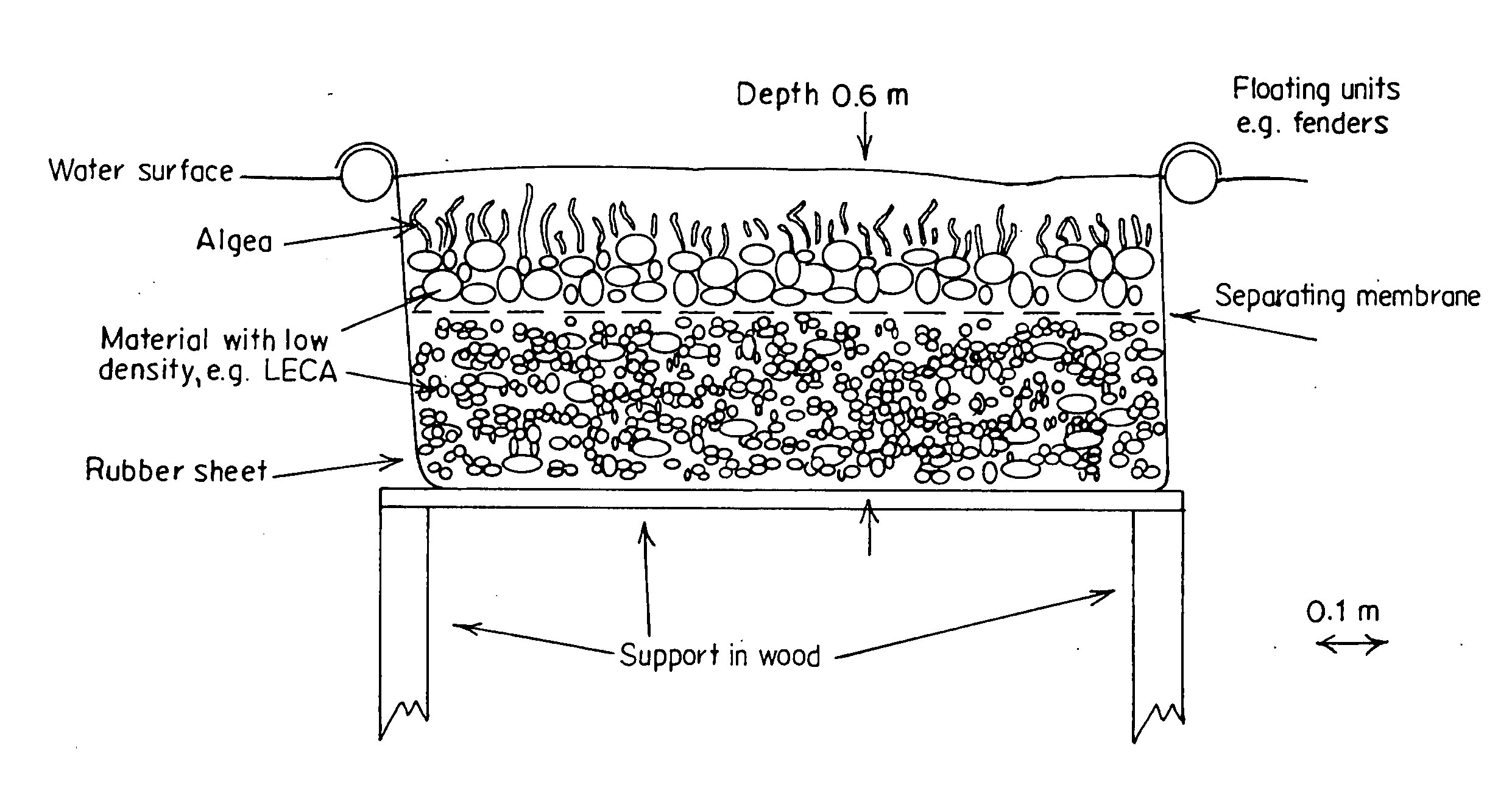
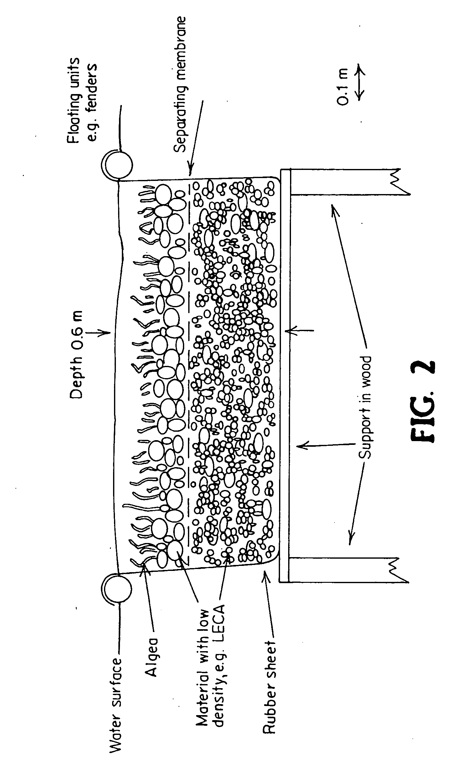
[0081]A shallow basin with a surface area from a few hundreds of square meters to a hectare is required. ...

example 2

Runoff Waters from Agricultural Land

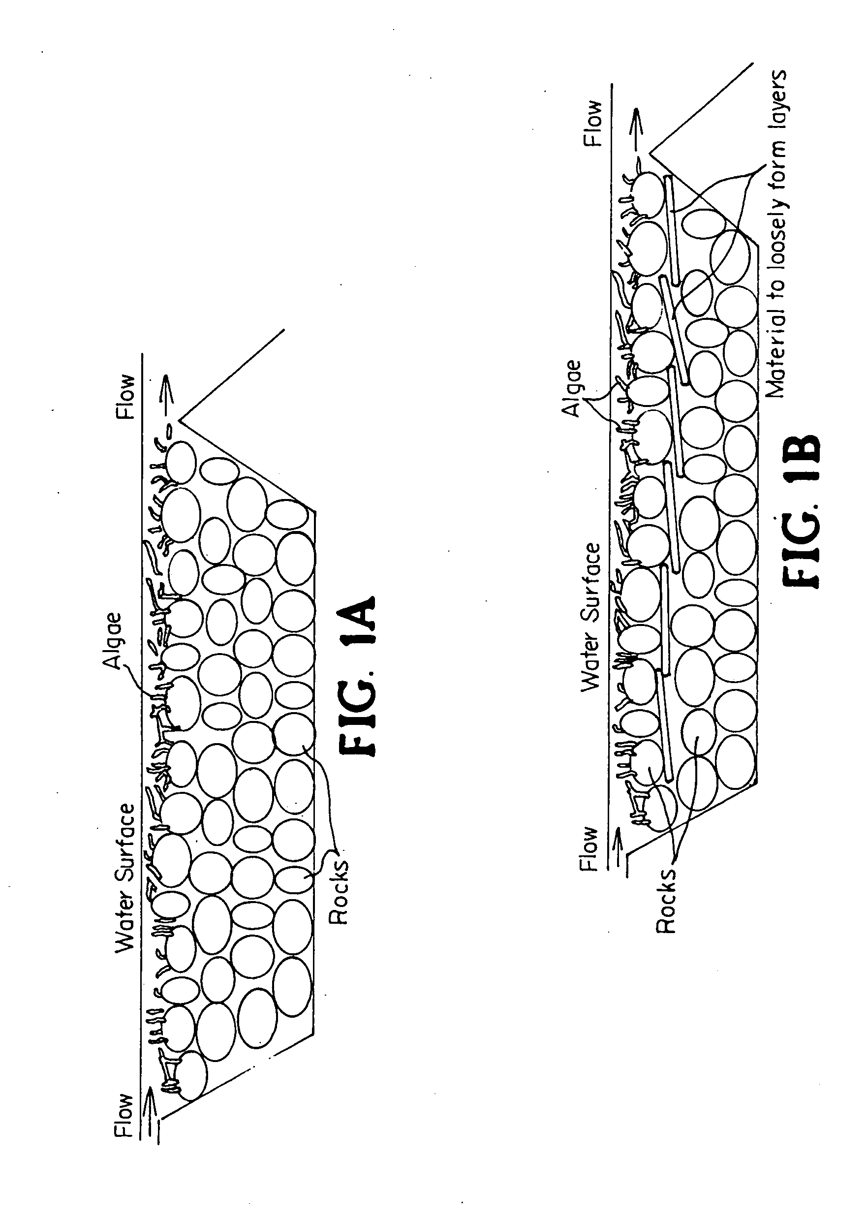
[0088]The heavy use of nutrients in agricultural activities causes major leakage (of nutrients such as nitrogen and phosphorus) to the landscape and recipients. Much of these nutrients are eventually transported in streams in the landscape. This invention is very suitable for, and easily applied, in such streams. The system of the invention can be constructed for a minimum environmental impact and alteration of natural occurring streams. It may be divided in several separated parts if desired and have little or no effect on the wildlife. For example, a parallel pond can be constructed next to the stream with an inlet upstream and an outlet downstream.

[0089]As in example 1, a two-layer system, with a membrane in between the layers, is constructed. The membrane might probably need to be thicker than in example 1, as the water from streams and runoff areas usually is more diluted and contains less oxygen-consuming particles. In order to calculate or ...


PUM

PropertyMeasurementUnit
depthaaaaaaaaaa
heightaaaaaaaaaa
heightaaaaaaaaaa

Abstract

A waste water treatment system is provided that includes a basin for holding water; nitrifying and denitrifying bacteria; macroalgae; and a biobed having a at least one layer and being constructed of materials selected to provide sufficient level of pH for enabling bacterial growth. In the biobed de-nitrification and nitrification bacterial processes are separated. Oxygen produced by algae is used by the nitrifying bacteria. Water is provided continuously to the biobed at an inlet and exits the system downstream after having gone through the biobed. The system may be used with waste water in water treatment plants, domestic waste water (sewage), waste water from diverse industries, drain water from waste deposits, runoff water from roads, water waste treatment and recycling plants, agricultural and farm land and surrounding land of populated areas. The algae and bacteria are combined for symbiotic remediation of water that may be flexibly controlled to adapt to a broad range of applications.

Description

CROSS-REFERENCE TO RELATED APPLICATIONS[0001]This application claims priority from U.S. Provisional Application Ser. No. 61 / 398,108 filed Jun. 21, 2010.FIELD OF THE INVENTION[0002]The present invention relates generally to water treatment plants, domestic waste water (sewage), waste water from diverse industries, drain water from waste deposits, runoff water from roads, water waste treatment and recycling plants, agricultural and farm land and surrounding land of populated areas. More specifically this invention combines algae and bacteria for symbiotic remediation of water in a new innovative geometric construction giving outstanding fine tuning control as well as flexibility to adapt to a broad range of applications.BACKGROUND OF THE INVENTION[0003]Large outlets of water affected by man are a major problem around the world. Cleaning wastewater, and in particular sewage is related to high costs and a high amount of waste products. Current methods for water cleaning include: mechani...

Claims


Application Information

Patent Timeline
Patent Type & Authority Applications(United States)
IPC IPC(8): C02F3/32C05F11/00C02F3/34C02F3/00C02F3/30
CPCC05F11/00C02F3/046Y02E50/343C02F3/325C02F3/302Y02E50/30Y02W10/10Y02W10/37Y02W30/40
Inventor CARR, HERMANLANDBERG, TOMMY
Owner CLEAR WATER ENERGY NORDIC
Why Eureka
Try Eureka