

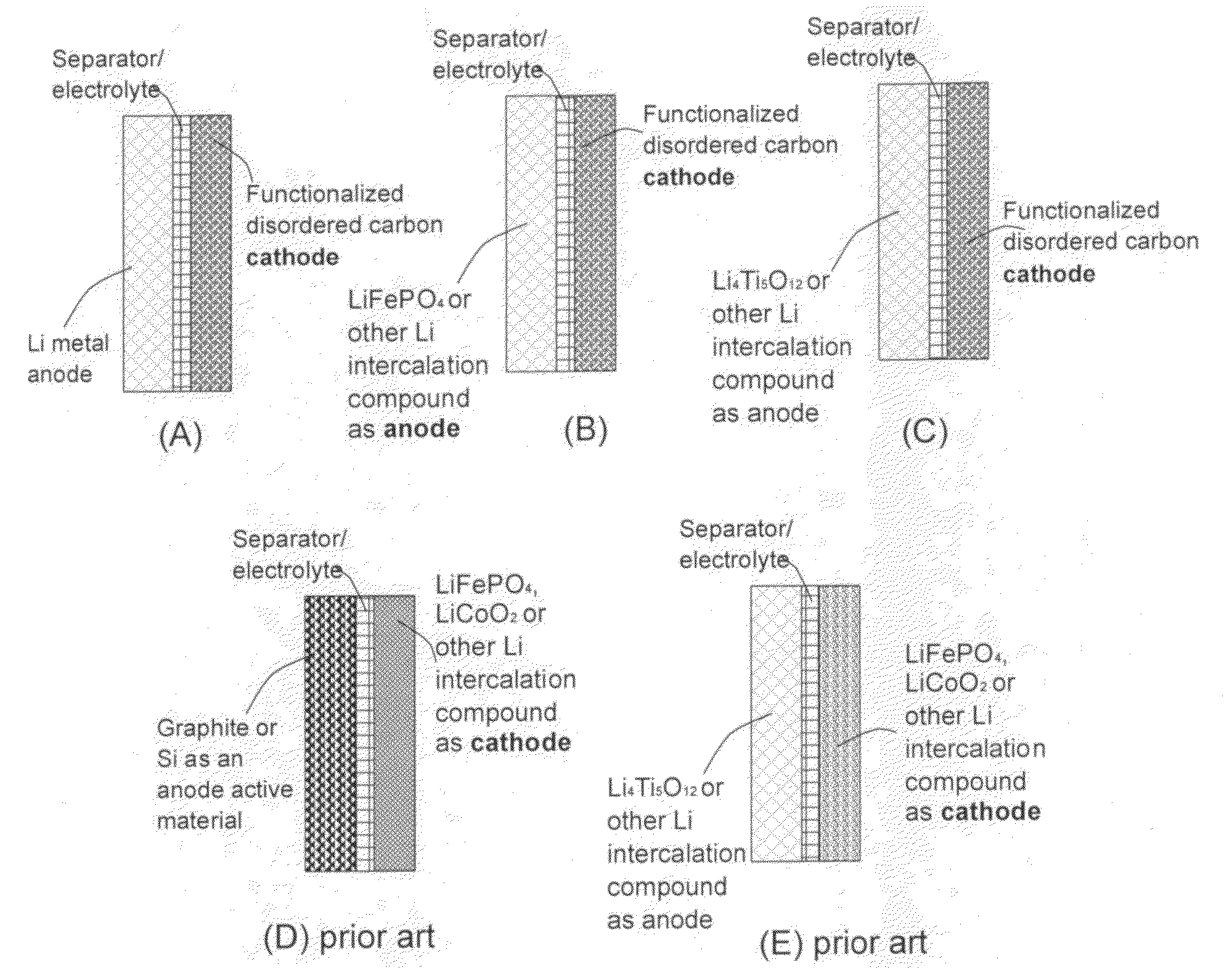
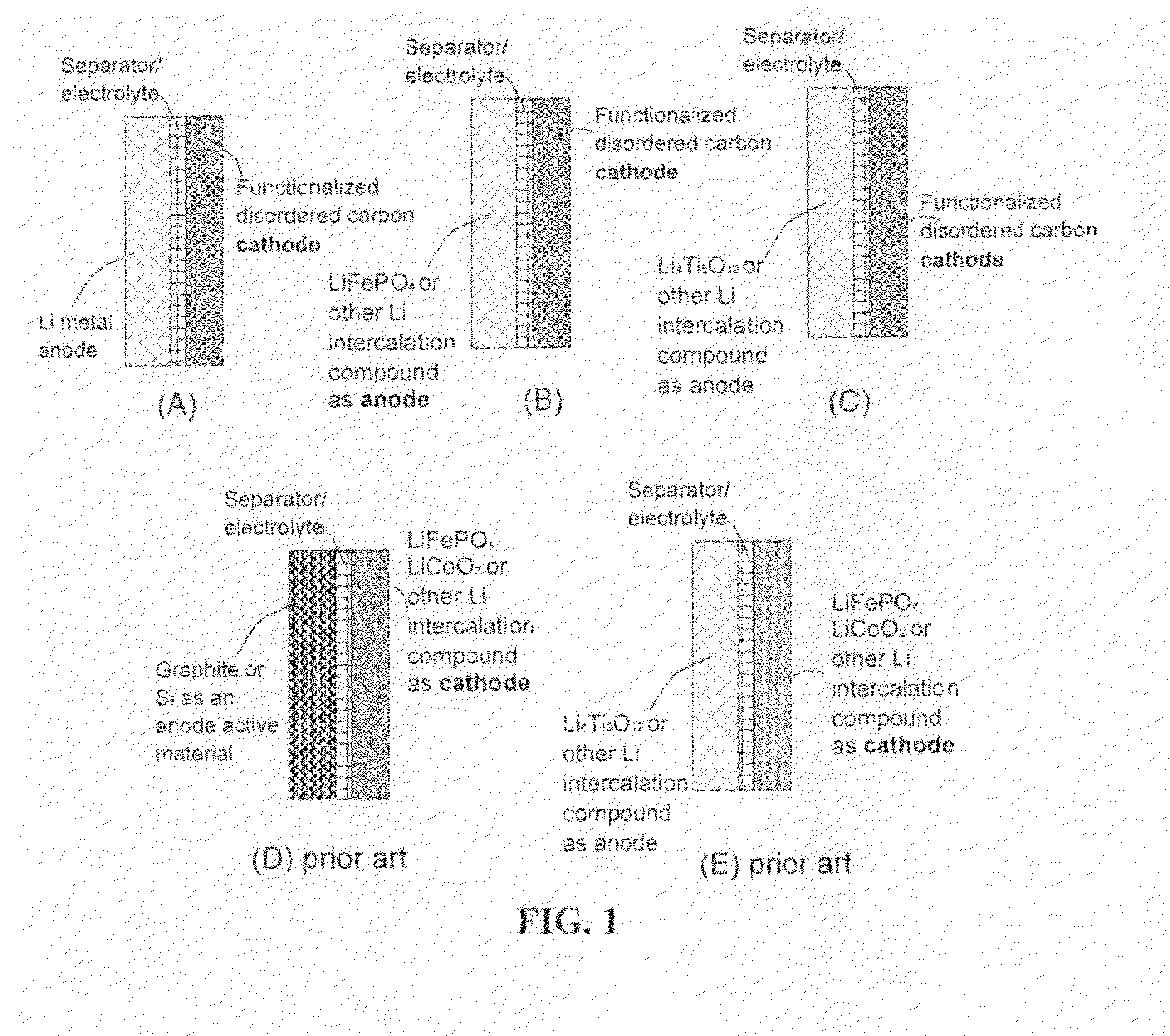
Lithium super-battery with a chemically functionalized disordered carbon cathode
a carbon cathode and super-battery technology, applied in the field of electrochemical energy storage devices, can solve the problems of requiring re-charge typically hours, delivering a very low power density (100-500 w/kg), and limiting the widespread implementation of super-capacitors for various industrial applications
- Summary
- Abstract
- Description
- Claims
- Application Information
AI Technical Summary
Problems solved by technology
Method used
Image

Examples
example 1
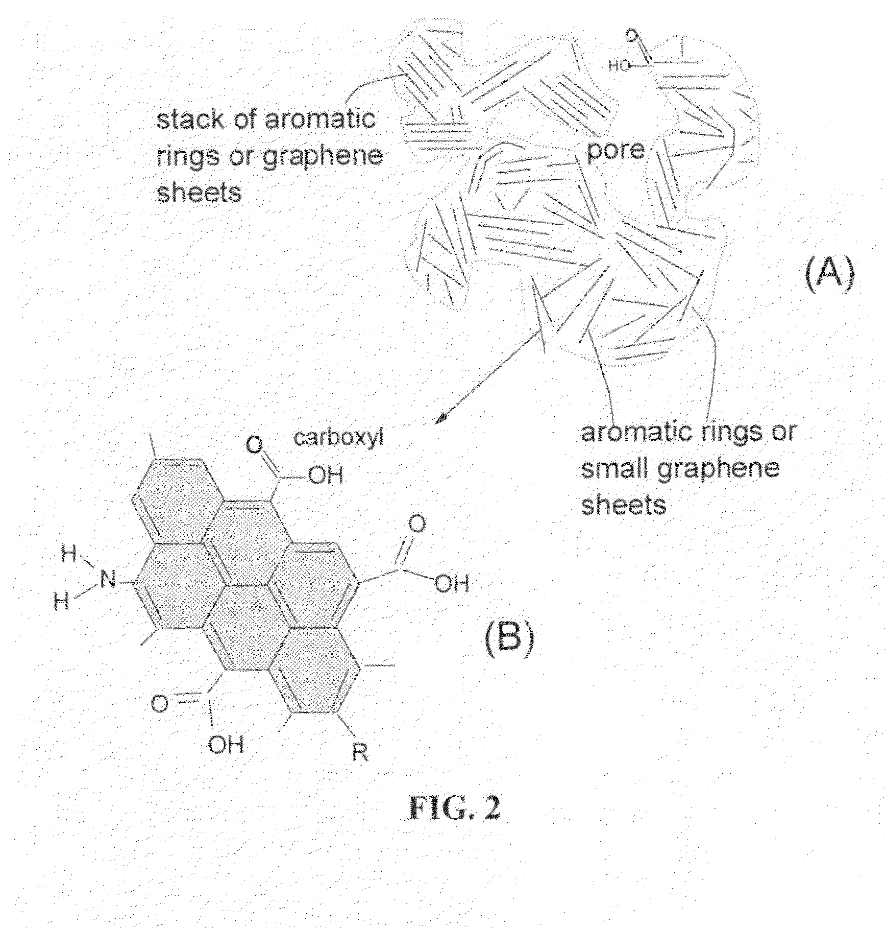
Functionalized Soft Carbon
[0082]Functionalized soft carbon was prepared from a liquid crystalline aromatic resin. The resin was ground with a mortar, and calcined at 900° C. for 2 h in a N2 atmosphere to prepare the graphitizable carbon or soft carbon. The resulting soft carbon was mixed with small tablets of KOH (four-fold weight) in an alumina melting pot. Subsequently, the soft carbon containing KOH was heated at 750° C. for 2 h in N2. Upon cooling, the alkali-rich residual carbon was washed with hot water until the outlet water reached a pH value of 7. The activated soft carbon was then immersed in a 90% H2O2-10% H2O solution at 45° C. for an oxidation treatment that lasted for 2 hours. Then, the resulting partially oxidized soft carbon was immersed in HCOOH at room temperature for functionalization for 24 hours. The resulting functionalized soft carbon was dried by heating at 60° C. in a vacuum for 24 hours.
[0083]Coin cells using functionalized soft carbon as the cathode and a ...
example 2
Functionalized Activated Carbon
[0089]Activated carbon (AC, from Ashbury Carbon Co.) was treated with an acid solution (sulfuric acid, nitric acid, and potassium permanganate at a ratio of 4:1:0.05) for 24 hours. Upon completion of the reaction, the mixture was poured into deionized water and filtered. The treated AC was repeatedly washed in a 5% solution of HCl to remove most of the sulphate ions. The sample was then washed repeatedly with deionized water until the pH of the filtrate was neutral. The slurry was subjected to further functionalization in formic acid at 25° C. for 30 minutes in an ultrasonication bath. Subsequently, dip-coating was used to obtain thin films of chemically functionalized activated carbon (f-AC) with a thickness of typically between 20 and 150 μm coated on a surface of an aluminized carbon layer as a current collector. In one case, the f-AC film was used as a cathode and a lithium foil was used as an anode. In another case, lithiated lithium titanate (LTO...
example 3
Needle Coke
[0091]Anisotropic needle coke produced in a commercial delayed coker was provided from
[0092]Nippon Steel Chemical Co. Ltd. The anisotropic coke had a fully developed needle-shape texture of optical anisotropy. Volatile species of the raw coke was estimated to be around 5 wt. %. Activation was carried out using KOH. The reaction apparatus consisted of a stainless tube and a nickel sample holder. KOH activation was carried out at 800° C. for 2 h under Ar flow, and coke / KOH ratio was varied between 1 / 1 and 1 / 4. The activated needle coke was then immersed in a H2SO4—NaNO3 mixture at 45° C. for an oxidation and functionalization treatment that lasted for 24 hours. The highest energy densities of a lithium super-battery featuring chemically functionalized needle coke a cathode active material (124 μm thick) and lithium foil as an anode active material was found to be approximately 321 Wh / kg. The highest power density was 24 Kw / Kg.
PUM
| Property | Measurement | Unit |
|---|---|---|
| pore size | aaaaa | aaaaa |
| pore size | aaaaa | aaaaa |
| specific surface area | aaaaa | aaaaa |
Abstract
Description
Claims
Application Information