Method and apparatus to laser ablation-laser induced breakdown spectroscopy

Active Publication Date: 2012-04-26
UNIV OF FLORIDA RES FOUNDATION INC
View PDF1 Cites 71 Cited by
  • Summary
  • Abstract
  • Description
  • Claims
  • Application Information

AI Technical Summary

Benefits of technology

[0009]Embodiments of the invention relate to a method and apparatus for analyzing a target material. Specific embodiments can be referred to as laser ablation laser-induced breakdown spectroscopy (LA-LIBS). Embodiments of the invention relate to the use of a first laser beam pulse incident on a target material to create an ablation event so as to produce an ablation plume of target material. Such ablation events can include, for example, plasma ablation, sub-plasma ablation, and thermal desorption. At least a portion of the ablation plume of target material can then be transported a sufficient distance away from the ablation event that a second laser beam pulse can interact with the at least a portion of the ablation plume of target material to create an analytical plasma such that the analytical plasma is uncoupled from the ablation event. The creation of the analytical plasma results in one or more elements of the at least a portion of the ablation plume of target material undergoing atomic emission, which can, optionally, be collected and analyzed. Referring to FIG. 1, a specific embodiment, the embodiment describes the use of separate laser-induced plasmas. The first plasma, referred to as the ablation plasma, is used to abla

Problems solved by technology

A fundamental problem with real time quantitative chemical analysis under the current state of technology is the non-linear analyte response that may occur when the composition of a sample's background matrix is altered.
For true quantitative analysis, calibration of the analytical tool is typically made with matrix matched samples, presenting limitations in performing in situ and real time analysis, and adding cost and complexity
ICP-AES enjoys high sensitivity, but drawbacks include the relatively high equipment costs and the need for sample preparation (i.e. digestion).
Drawbacks of ICP-MS include relatively higher equipment costs and complexity as compared to ICP-AES, and the required sample preparation (i.e., digestion).
The drawbacks include additional cost and complexity, as well as the potential for introduction of matrix effects during the laser ablation step.
However, the laser ablation step can introduce additional matrix effects due to things like (1) non-stoichiometric ablation, in which the ablation plume elemental concentrations do not match the elemental concentrations of the original solid material, and (2)

Method used


Image

  • Method and apparatus to laser ablation-laser induced breakdown spectroscopy
  • Method and apparatus to laser ablation-laser induced breakdown spectroscopy
  • Method and apparatus to laser ablation-laser induced breakdown spectroscopy

Examples


example 1

[0035]Seven standard reference materials were investigated, in which 5 elements (Al, Mn, Mg, Fe, and Cu) were analyzed. Four of the standards were from the National Institute of Standards and Technology (NIST), namely NIST-1242 (a cobalt-chromium rich high temperature alloy), NIST-1276a (a cupro-nickel alloy), NIST-1297 (a stainless steel), and NIST-1761 (a low alloy steel). Three samples were cast aluminum standards from Apex Smelting Company (SM-9, SM-10 and S-11). Table 1 gives the certified concentration values, in percentage by mass, for the 5 selected analyte species in all seven standards, as well as other dominant elements present in sample matrix. All the standards were machined into sample coupons (square or round) with a diameter of 2.5 cm and a thickness of 2 to 3 mm.

TABLE 1Concentration (% by mass) of the five analytical elements present ineach certified standard, along with other prominent elements.Concentration (% by mass)Apex Smelting Co.NISTElementSM-9SM-10S-1112421...

example 2

[0052]The effects of carrier gas were examined using the same experimental conditions for Example 1 for the SM-10 reference sample. The laser ablation LIBS measurements were repeated for a pristine SM-10 sample using the identical experimental methodology, but with the nitrogen carrier gas replaced with a carrier gas flow of pure helium at a rate of 1.5 lpm. While no detailed optimization was performed, a better analyte response was observed for the helium carrier gas, as compared to the nitrogen carrier gas. FIG. 9 presents representative spectra for the laser ablation LIBS measurements as recorded in nitrogen and helium carrier gases. Examination of the two spectra reveals a reduction in spectral noise with the change to helium. The signal-to-noise ratio (SNR) was used to assess the improvements in analytical performance with helium. The signal-to-noise values were calculated by taking the ratio of the full-peak area to the rms-noise, as measured from the adjacent continuum emissi...

example 3

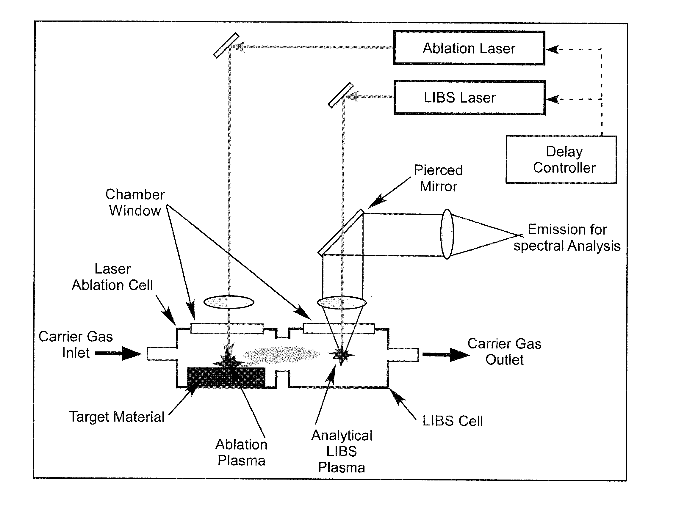
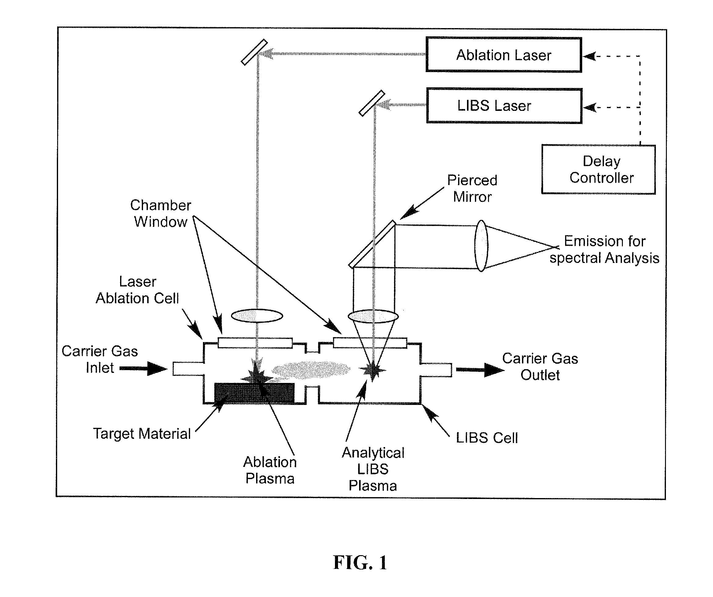
[0053]The effects of carrier gas flow rate were examined using experimental conditions similar to Example 1, but with the following changes. The laser ablation event was performed with a frequency-tripled Nd:YAG laser at 355-nm wavelength and pulse energy of 40 mJ / pulse. The analytical laser-induced plasma was created using a fundamental Nd:YAG laser at 1064-nm wavelength and pulse energy of 200 mJ / pulse. The ablation cell was of diameter about 1⅜″ with a height (target to quartz window) of about 0.9″. An inlet of about 3 / 16″ diameter allowed carrier gas to enter the ablation cell and an diametrically opposed outlet of about 3 / 16″ diameter allowed the carrier gas and ablation plume to exit the ablation cell. The exit was directly coupled to an adjoining laser-induced plasma cell by a single tube about 2″ long and about 3 / 16″ diameter. The tube exited directly at the focal spot of the analytical laser-induced plasma, which sampled the ablation plume. The two laser pulses were synchro...


PUM


Abstract

Embodiments of the invention relate to a method and apparatus for analyzing a target material. Specific embodiments can be referred to as laser ablation laser-induced breakdown spectroscopy (LA-LIBS). Embodiments of the invention relate to the use of a first laser beam pulse incident on a target material to create an ablation event so as to produce an ablation plume of target material. Such ablation events can include, for example, plasma ablation, sub-plasma ablation, and thermal desorption. At least a portion of the ablation plume of target material can then be transported a sufficient distance away from the ablation event that a second laser beam pulse can interact with the at least a portion of the ablation plume of target material to create an analytical plasma such that the analytical plasma is uncoupled from the ablation event. The creation of the analytical plasma results in one or more elements of the at least a portion of the ablation plume of target material undergoing atomic emission, which can, optionally, be collected and analyzed.

Description

CROSS-REFERENCE TO RELATED APPLICATION[0001]The present application claims the benefit of U.S. Provisional Application Ser. No. 61 / 224,506, filed July 10, 2009, which is hereby incorporated by reference herein in its entirety, including any figures, tables, or drawings.STATEMENT REGARDING FEDERALLY SPONSORED RESEARCH OR DEVELOPMENT[0002]The subject invention was made with government support under a research project supported by National Science Foundation, Contract No. CHE-0822469. The government has certain rights to this invention.BACKGROUND OF INVENTION[0003]A fundamental problem with real time quantitative chemical analysis under the current state of technology is the non-linear analyte response that may occur when the composition of a sample's background matrix is altered. The inconsistencies that occur when investigating an analyte in different material matrices are generally referred to as matrix effects. For true quantitative analysis, calibration of the analytical tool is t...

Claims


Application Information

Patent Timeline
IPC IPC(8): G01J3/30
CPCG01N21/718
Inventor HAHN, DAVID WORTHINGTON
Owner UNIV OF FLORIDA RES FOUNDATION INC
Why Eureka
Try Eureka