High-frequency electroporation for cancer therapy

a high-frequency electroporation and cancer technology, applied in the field of biomedical engineering and medical treatment of diseases and disorders, can solve the problems of not being able to accurately predict the electric field distribution, prior knowledge of how the conductivity of a tissue is modulated in response to electroporation is not required, and achieves the effect of increasing current storage, reducing the total capacitance of the bank, and effective analog bandwidth

Active Publication Date: 2012-05-03
VIRGINIA TECH INTPROP INC
View PDF12 Cites 123 Cited by
  • Summary
  • Abstract
  • Description
  • Claims
  • Application Information

AI Technical Summary

Benefits of technology

[0013]It is possible for the electric field to penetrate tissue heterogeneities when high-frequency electric fields are employed, because capacitive coupling is enhanced allowing current to flow through both extracellular and intracellular spaces. See Gowrishankar, T. R. and J. C. Weaver, An approach to electrical modeling of single and multiple cells. Proceedings of the National Academy of Sciences of the United States of America, 2003. 100(6): p. 3203-3208; and Ivorra, A., ed. Tissue Electroporation as a Bioelectric Phenomenon: Basic Concepts. Irreversible Electroporation, ed. B. Rubinsky. 2010, Springer Berlin Heidelberg. 23-61. In this case, all cells present in the organ, regardless of their packing and morphology, experience a macroscopically homogeneous electric field distribution. See Esser, A. T., K. C. Smith, T. R. Gowrishankar, and J. C. Weaver, Towards Solid Tumor Treatment by Nanosecond Pulsed Electric Fields. Technology in Cancer Research & Treatment, 2009. 8(4): p. 289-306. This results in more predictable and uniform treatment outcomes without the electric energy being preferentially deposited into regions of tissue with a lower passive conductivity. As a result, Joule heating is also more uniformly distributed throughout the tissue, which mitigates the potential for thermal damage in regions with a low passive conductivity.
[0014]Enhanced capacitive coupling also limits the change in tissue electrical conductivity due to electroporation. Therefore, prior knowledge of how the conductivity of a tissue is modulated in response to electroporation is not required to accurately predict the electric field distribution. As a result, simplified algorithms can be implemented for treatment planning.
[0016]Clinically, this translates to performing IRE without the requirement of paralytic agents (or a reduction in the amount of paralytic agents administered) in all procedures, and without the further requirement of general anesthesia in minimally invasive procedures. Additionally, other complications caused by IRE with unipolar electric pulses are alleviated, including electrode displacement and pain associated with intense muscle contractions.
[0019]More specifically, the present invention provides new devices and methods for the treatment of diseases and disorders, such as hemic and solid neoplasias, which improves conventional clinical practice associated with electroporating target tissues.
[0034]Methods of the invention may or may not employ administering of a drug designed to induce a neural blockade. The methods can include administration of general, local, or no anesthesia for treatment of tissues with electroporation based therapies. In preferred embodiments, no neural blockade is required for treatment of tissues with electroporation based therapies, or lower dosages of a neural blockade can be used in embodiments of the invention to achieve the same results as using higher doses with lower frequency pulsing protocols.
[0037]Treatment planning according to embodiments of the invention can result in more predictable outcomes in homogeneous and heterogeneous tissues than compared with lower frequency pulsing protocols.

Problems solved by technology

Enhanced capacitive coupling also limits the change in tissue electrical conductivity due to electroporation.
Therefore, prior knowledge of how the conductivity of a tissue is modulated in response to electroporation is not required to accurately predict the electric field distribution.

Method used


Image

  • High-frequency electroporation for cancer therapy
  • High-frequency electroporation for cancer therapy
  • High-frequency electroporation for cancer therapy

Examples


example 1

[0088]High-frequency electroporation results in more uniform and predictable treatment outcomes in heterogeneous tissues.

[0089]A 2D axisymmetric FEM representative of a cylindrical section of non-infiltrated fat encapsulated by dry skin was simulated using COMSOL 3.5a (Burlington, Mass.). The electric potential distribution within the tissue was obtained by transiently solving:

-∇·(σ∇Φ)-ɛ0ɛr∇·(∂∇Φ∂t)=0(7)

[0090]where Φ is the electric potential and σ and εr are the conductivity and relative permittivity of each tissue layer, respectively, which depends on frequency (Table 1). Equation (7) is obtained from Maxwell's equations assuming no external current density (J=σE), no remnant displacement (D=ε0εrE), and the quasi-static approximation. This approximation implies a negligible coupling between the electric and magnetic fields (∇×E=0), which allows for the expression of electric field only in terms of electric potential:

E=−ΛΦ  (8)

[0091]Dielectric properties of the bulk tissue were cho...

example 2

[0094]High-frequency electroporation results in homogeneous energy deposition and reduces the potential for thermal damage in low passive conductivity tissue.

[0095]The temperature distribution in the model described in EXAMPLE 1 was obtained by transiently solving a modified version of the Pennes bioheat equation (see Pennes, H. H., Analysis of tissue and arterial blood temperatures in the resting human forearm. J Appl Physiol, 1948. 1(2): p. 93-122) with the inclusion of a Joule heating term:

ρC∂T∂t=∇·(k∇T)+ρbωbCb(Tb-T)+Qm+J·E(9)

[0096]where T is the tissue temperature, Tb is the blood temperature, k is the thermal conductivity of the tissue, C and Cb are the tissue and blood specific heat, respectively, ρ and ρb are the tissue and blood density, respectively, Qm is the metabolic heat source term, ωb is the blood perfusion coefficient, and |J·E| is the Joule heating term. All thermal tissue properties are given in Table 3. Fiala, D., K. J. Lomas, and M. Stohrer, A computer model of h...

example 3

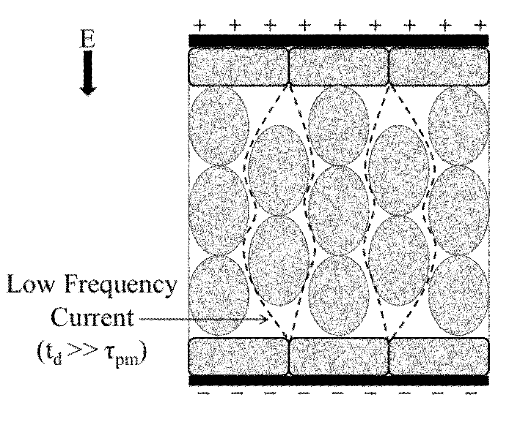
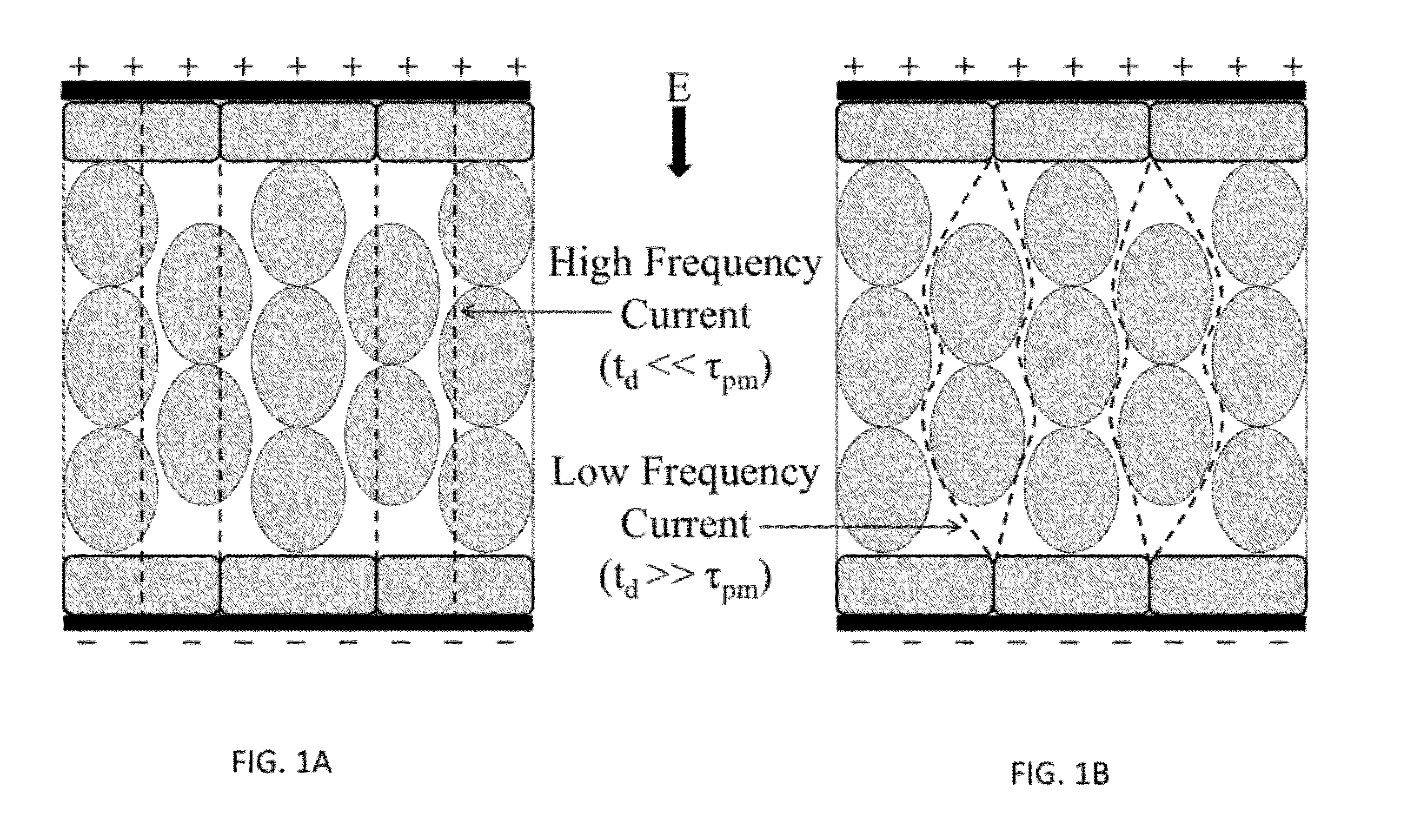
[0102]High-frequency electroporation can overcome shielding effects of low passive conductivity tissues and induce electroporation in underlying layers.

[0103]The analytical model for TMP described in this specification was utilized to investigate electroporation in a hypothetical cell located along the centerline (r=0 mm) in the middle of the fat (z=0) and skin (z=5.75 mm) layers of the FEM described in EXAMPLE 1. The equations for TMP are derived under the assumption that there is no influence on the microscopic electric field from neighboring cells. Therefore, the macroscopic electric field in the bulk tissue predicted by the FEM dictates the microscopic electric field experienced by the cell. The vertical z-component of the electric field was imported from the specific locations within FEM into Mathematica to account for polarity changes. The radial r-component was neglected due to the fact that it never surpassed 3 V / cm as current traveled primarily in the z-direction. Non-unifo...


PUM


Abstract

The present invention relates to the field of biomedical engineering and medical treatment of diseases and disorders. Methods, devices, and systems for in vivo treatment of cell proliferative disorders are provided. In embodiments, the methods comprise the delivery of high-frequency bursts of bipolar pulses to achieve the desired modality of cell death. More specifically, embodiments of the invention relate to a device and method for destroying aberrant cells, including tumor tissues, using high-frequency, bipolar electrical pulses having a burst width on the order of microseconds and duration of single polarity on the microsecond to nanosecond scale. In embodiments, the methods rely on conventional electroporation with adjuvant drugs or irreversible electroporation to cause cell death in treated tumors. The invention can be used to treat solid tumors, such as brain tumors.

Description

CROSS-REFERENCE TO RELATED APPLICATIONS[0001]The present application relies on and claims priority to and the benefit of the filing date of U.S. Provisional Patent Application No. 61 / 424,872 filed Dec. 20, 2010 and International Patent Application No. PCT / US11 / 66239, filed Dec. 20, 2011; and the present application is a Continuation-In-Part (CIP) application of U.S. ptent application Ser. No. 12 / 757,901, filed Apr. 9, 2010, which relies on and claims priority to and the benefit of the filing date of U.S. Provisional Patent Application Nos. 61 / 167,997, filed Apr. 9, 2009 and 61 / 285,618 filed Dec. 11, 2009. The entire disclosures of all of these patent applications are hereby incorporated herein by reference.STATEMENT OF GOVERNMENT INTEREST[0002]This invention was made with government support under Contract No. CBET-0933335 awarded by National Science Foundation. The government has certain rights in the invention.BACKGROUND OF THE INVENTION[0003]1. Field of the Invention[0004]The pres...

Claims


Application Information

Patent Timeline
Patent Type & Authority Applications(United States)
IPC IPC(8): A61B18/00
CPCA61B18/14A61B2018/0016A61B2018/00613A61B2018/00767A61B2018/00577A61B2018/00761A61N1/327A61B2018/126A61B2018/00732A61B2017/00159A61B2017/00172
Inventor ARENA, CHRISTOPHER B.DAVALOS, RAFAEL V.SANO, MICHAEL B.
Owner VIRGINIA TECH INTPROP INC
Why Eureka
Try Eureka