Optical fiber delivery system for delivering optical short pulses and optical fiber delivery method

a technology of optical fiber and optical short pulse, which is applied in the direction of optics, optical elements, instruments, etc., can solve the problems of reducing the communication rate or increasing the symbol error rate, and affecting the performance of the optical fiber delivery system. , to achieve the effect of high peak power

Active Publication Date: 2012-05-31
OLYMPUS CORP
View PDF2 Cites 14 Cited by
  • Summary
  • Abstract
  • Description
  • Claims
  • Application Information

AI Technical Summary

Benefits of technology

[0054]receiving an optical short pulse having high peak power, and transmitting the optical short pulse through the nonlinear effect generation unit, to thereby provide a nonlinear ef

Problems solved by technology

Such temporal broadening of an optical pulse leads to problems in many applications.
For example, in the field of processing, thermal deformation of metal simultaneously occurs during metal cutting or the like, and hence the pulse broad

Method used


Image

  • Optical fiber delivery system for delivering optical short pulses and optical fiber delivery method
  • Optical fiber delivery system for delivering optical short pulses and optical fiber delivery method
  • Optical fiber delivery system for delivering optical short pulses and optical fiber delivery method

Examples


first embodiment

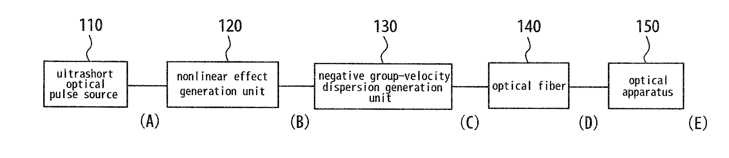
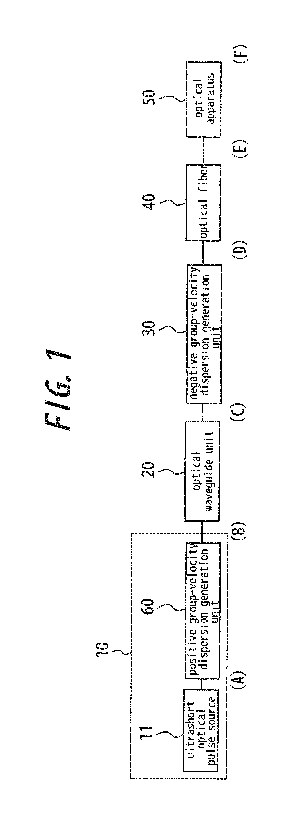
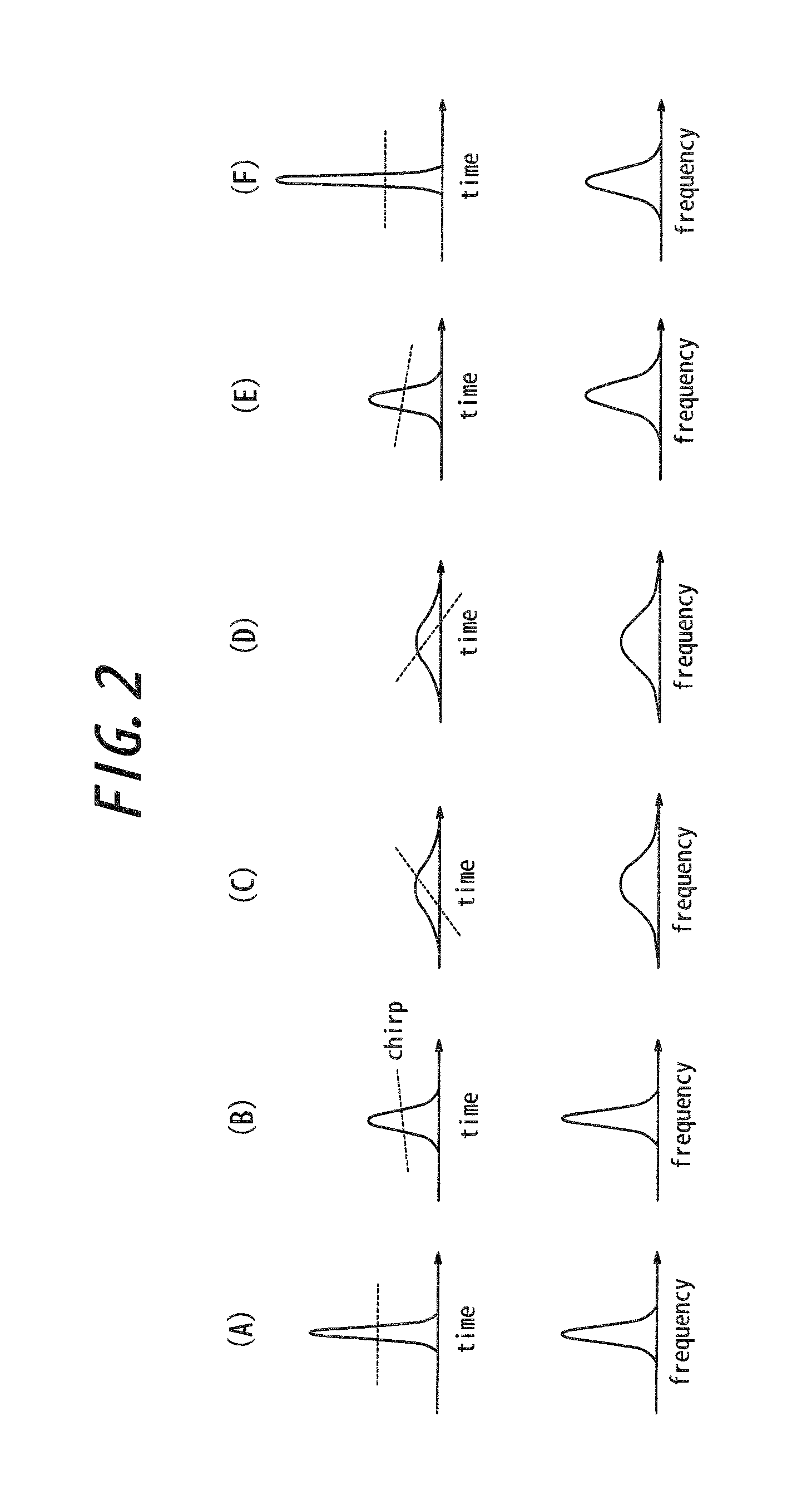
[0081]FIGS. 1 and 2(A) to 2(F) each illustrate a first embodiment of the present invention. FIG. 1 is a block diagram illustrating a schematic configuration of an optical system having an optical fiber delivery system for delivering optical short pulses, and FIGS. 2(A) to 2(F) show temporal waveforms (upper side) and spectral waveforms (lower side) of an optical pulse in the portions (A) to (F) of FIG. 1, respectively. In FIG. 2, the broken lines on the temporal waveforms on the upper side each indicate a chirp.

[0082]The optical system according to this embodiment includes: a chirp pulse source 10; optical waveguide unit 20; negative group-velocity dispersion generation unit 30; an optical fiber 40; and an optical apparatus 50 that has positive GVD and uses optical short pulses.

[0083]The chirped pulse source 10 includes an ultrashort optical pulse source 11 and positive group-velocity dispersion generation unit 60. The ultrashort optical pulse source 11 employs an optical pulse sour...

second embodiment

[0101]FIG. 5 is a block diagram illustrating a schematic configuration of an optical system having an optical fiber delivery system for delivering optical short pulses according to a second embodiment of the present invention. In this embodiment, positive group-velocity dispersion addition unit 70 for providing a positive GVD effect is disposed between the optical fiber 40 and the optical apparatus 50 of the first embodiment in order to adjust the down chirp of the optical short pulse incident on the optical apparatus 50, to thereby obtain an ultrashort optical pulse having high peak power and a desired temporal width at a desired position in the optical apparatus 50. Here, the positive group-velocity dispersion addition unit 70 is configured by including, for example, any one of the following optical components: a light-transmitting substrate such as a glass rod; a lens; an acousto-optic modulator; a diffraction grating; and a prism.

[0102]The positive group-velocity dispersion addi...

third embodiment

[0107]FIG. 7 is a diagram illustrating a configuration of an optical system having an optical fiber delivery system for delivering optical short pulses according to a third embodiment of the present invention. In this embodiment, the optical fiber delivery system for delivering optical short pulses of FIG. 5 is applied to an endoscope. This optical system employs, as the ultrashort optical pulse source 11, a titanium:sapphire mode-locked laser 12 that produces optical pulses each having an oscillation wavelength of approximately 980 nm, a pulse width of approximately 120 fs, a repetition rate of 90 MHz, and an average optical output power of approximately 0.8 W.

[0108]Further, the positive group-velocity dispersion generation unit 60 employs an acousto-optic module (AOM) 62. The AOM 62 is capable of converting the up-chirped ultrashort optical pulses emitted from the ultrashort optical pulse source 11 into up-chirped optical short pulses, and also modulating the output intensity ther...


PUM


Abstract

The optical fiber delivery system for delivering optical short pulses includes: a chirped pulse source (10) for emitting an up-chirped optical short pulse having high peak power; optical waveguide unit (20) for delivering the optical short pulse emitted from the chirped pulse source (10); negative group-velocity dispersion generation unit (30) for providing negative group-velocity dispersion to the optical short pulse exited from the optical waveguide unit (20); and an optical fiber (40) for delivering the optical short pulse exited from the negative group-velocity dispersion generation unit (30), along a desired distance, in which the optical short pulse emitted from the chirped pulse source (10) is adapted to be exited, from the optical fiber (40), as a down-chirped optical short pulse that is substantially free of waveform distortion resulting from higher-order dispersion.

Description

CROSS REFERENCE TO RELATED APPLICATIONS[0001]The present application claims priority from Japanese Patent Applications No. 2010-267519 filed on Nov. 30, 2010, and No. 2010-293572 filed on Dec. 28, 2010, the contents of which are incorporated herein by reference.TECHNICAL FIELD[0002]The present invention relates to an optical fiber delivery system for delivering optical short pulses and an optical fiber delivery method.RELATED ART[0003]In recent years, sub-picosecond optical short pulses, having high peak power and a plurality of wavelength components, have been used in various fields, such as biology, medicine, medical care, processing, measurement, and communication. In particular, in the fields of biology and medicine, an optical pulse source that generates optical short pulses, such as a titanium:sapphire laser and a fiber laser, has been frequently used in a microscope using nonlinear optical effects, such as a multiphoton fluorescence microscope, a harmonic generation microscop...

Claims


Application Information

Patent Timeline
IPC IPC(8): G02F1/365G02F2/02H04B10/508
CPCH01S3/0057H04B10/508H01S3/0092H04B10/50
Inventor FUJIWARA, MASATOTAIRA, KENJI
Owner OLYMPUS CORP
Why Eureka
Try Eureka