Multi-path, multi-magnification, non-confocal fluorescence emission endoscopy apparatus and methods

a fluorescence emission endoscopy and multi-magnification technology, applied in the field of fluorescence emission and collection and/or imaging, and/or nonlinear harmonic emission collection and/or imaging, can solve the problems of non-uniform spatial coverage and sampling time of resonant devices in comparison to current miniaturized raster scanners, and the use of high energy light could easily damage living tissue in the entire region of exposure, etc., to achieve the effect of reducing the size of the scan

Active Publication Date: 2012-06-07
CORNELL UNIVERSITY
View PDF1 Cites 28 Cited by
  • Summary
  • Abstract
  • Description
  • Claims
  • Application Information

AI Technical Summary

Benefits of technology

[0073]In various exemplary applications, the apparatus and method embodiments described herein can be used to provide in vivo, in situ microscopic imaging of the infrastructure and bio-chemistry of tissue as a shortcut to diagnostic information that ordinarily would be later acquired by a pathologist's hematoxylin and eosin (H&E) stained absorption microscopy of fixed thin slices of tissue obtained by biopsy. The embodied apparatus and methods of the present invention may be utilized during surgery or during precursor diagnostics to delineate bou

Problems solved by technology

The use of high energy light could easily damage living tissue in the entire region of exposure.
Of these scanners, the resonant-based spiral scanners are the most successful in terms of their miniaturized dimensions (e.g., OD≈1 mm) and fast image acquisition speeds (e.g., 8 frames/s with 512×512 pixels per frame, ≈200 μm diameter FOVxy); however, these resonant devices are fundamentally limited by non-uniform spatial coverage and sampling time in comparison to current miniaturized raster scanners.
Current miniaturized raster scanners are, however, limited in terms of their physical dimen

Method used


Image

  • Multi-path, multi-magnification, non-confocal fluorescence emission endoscopy apparatus and methods
  • Multi-path, multi-magnification, non-confocal fluorescence emission endoscopy apparatus and methods
  • Multi-path, multi-magnification, non-confocal fluorescence emission endoscopy apparatus and methods

Examples


Embodiment Construction

[0092]Embodiments of the invention pertain generally to laser scanning, fluorescence emission microscopy systems and methods, and components, and applications thereof.

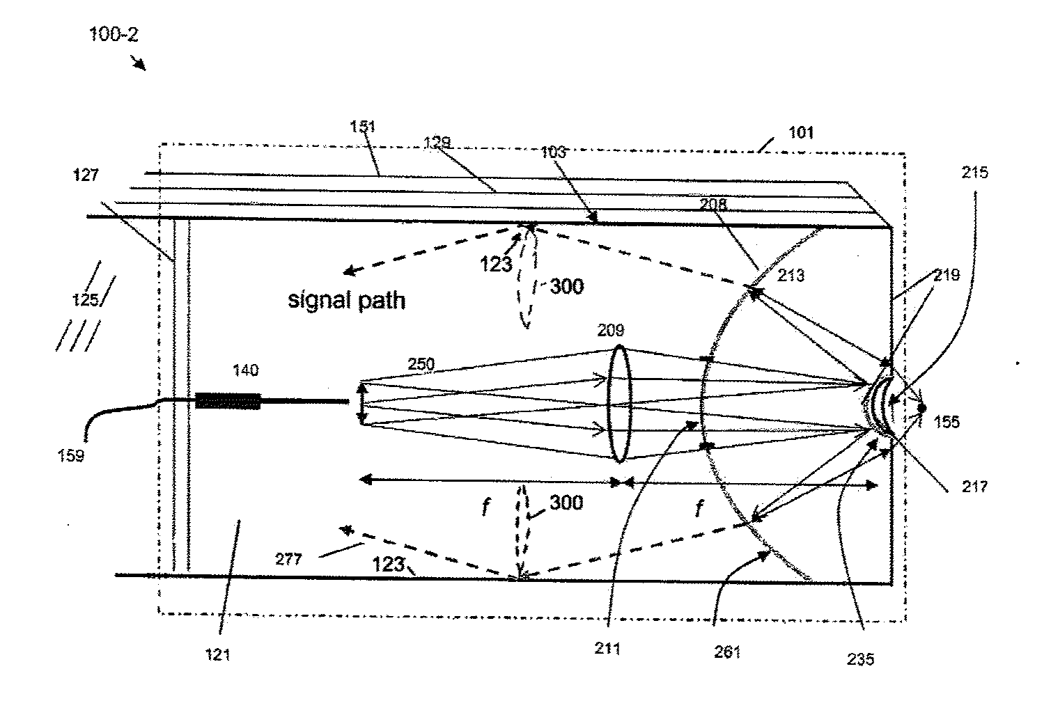
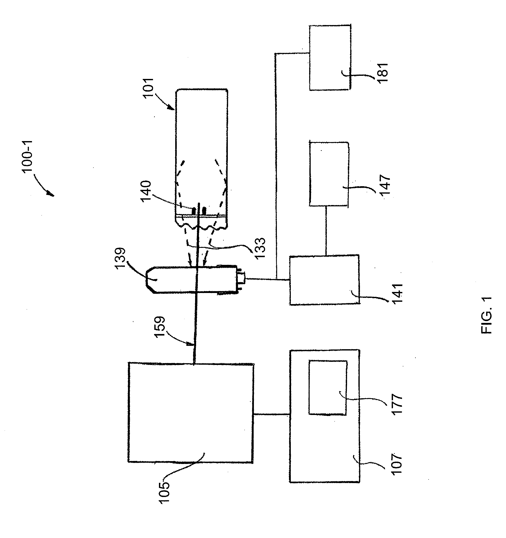
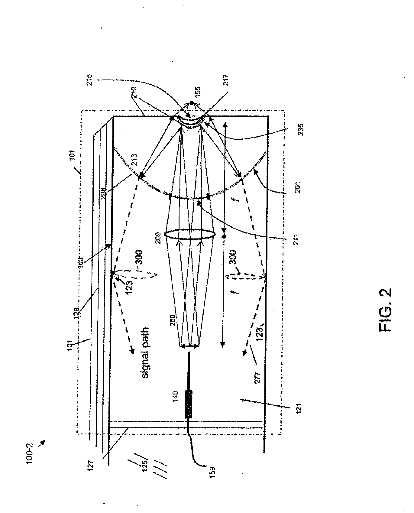
[0093]FIG. 1 shows a schematic diagram of a coaxial endoscope system 100-1 that is shown with a distal segment 101 that incorporates an optical system embodied by the invention. As described herein, the distal segment can be that of an endoscope or alternatively, may be a biopsy needle. The system is coaxial because, as shown, an optical fiber 159 that provides near IR target excitation light is coaxially surrounded, in part, by a light transmitting interior of the distal segment 101. The fluorescence emission endoscopy system 100-1 includes an illumination platform 105 that includes a suitable fluorescence emission excitation source such as a femtosecond, pulsed laser and a source of visible target illumination. An illumination platform control module 107 provides, for example, pulse shape control, beam expansion, spa...


PUM


Abstract

An optical scanner, scanner apparatus, or scanner assembly, which may be particularly advantageous for use in a multiphoton microscope, includes a first drivable bending component, a second drivable bending component mounted perpendicularly to the first component, and at least one optical waveguide coupled one or both of the first and second bending components, wherein the at least one optical waveguide provides both a propagation path for a multiphoton excitation radiation delivery between a light source and a target and a multiphoton-induced emission radiation delivery between the target and a detector. A GRIN relay lens. A multiphoton microscope incorporating the scanner and the GRIN relay lens.

Description

CROSS-REFERENCE TO RELATED APPLICATIONS[0001]This application is a continuation-in-part of, and claims priority to, U.S. application Ser. No. 12 / 742,562 filed on May 12, 2010, which is a US national stage filing of PCT / US2008 / 083164 filed on Nov. 12, 2008, which claims priority to U.S. Provisional application Ser. No. 60 / 987,868 filed on Nov. 14, 2007, and to U.S. Provisional application Ser. No. 60 / 987,270 filed on Nov. 12, 2007, the subject matters of all of which are incorporated by reference herein in their entireties.STATEMENT REGARDING FEDERALLY SPONSORED RESEARCH OR DEVELOPMENT[0002]This invention was made with government support under Grant No. 1R01EB006736-01 and Grant No. 5-P41EB001976 sponsored by the National Institute of Biological Imaging and Bioengineering at the National Institutes of Health, and National Institute of Health / National Cancer Institute Grant R01-CA133148. The government has certain rights in the invention.BACKGROUND OF THE INVENTION[0003]1. Field of th...

Claims


Application Information

Patent Timeline
IPC IPC(8): G02B26/10
CPCG02B21/16G02B23/243G02B23/2484G02B3/00G02B26/103G02B2207/114G02B23/26
Inventor WEBB, WATT W.SCHERR, DOUGLAS S.OUZOUNOV, DIMITRE GUEORGUIEVRIVERA, DAVID R.BROWN, CHRISTOPHER M.KOBAT, DEMIRHANHULAND, DAVIDHOWARD, SCOTT S.
Owner CORNELL UNIVERSITY
Why Eureka
Try Eureka