
Method for dewatering water-containing organic substance

Active Publication Date: 2012-06-21
HITACHI ZOSEN CORP
View PDF9 Cites 12 Cited by
  • Summary
  • Abstract
  • Description
  • Claims
  • Application Information

AI Technical Summary

Benefits of technology

[0035]For clarifying the effectiveness of the present invention, herein described is the significant energy-saving performance improvement by addition of a novel technique while the core part of the VP part including the operation condition therein is kept entirely the same; however, the effectiveness of the invention does not overstep the real nature of the invention even though the system, the instrument or the operation condition may be improved or modified in some degree by ordinary knowledge of those skilled in the art. Like in the description of the already-existing technique given hereinabove, the invention will be described for the system for water removal or dewatering of an aqueous ethanol solution; however, needless-to-say, the invention should include any and every water-containing organic substance to which ordinary VP is directed.
[0036]A basic method of dewatering in the invention is as follows.
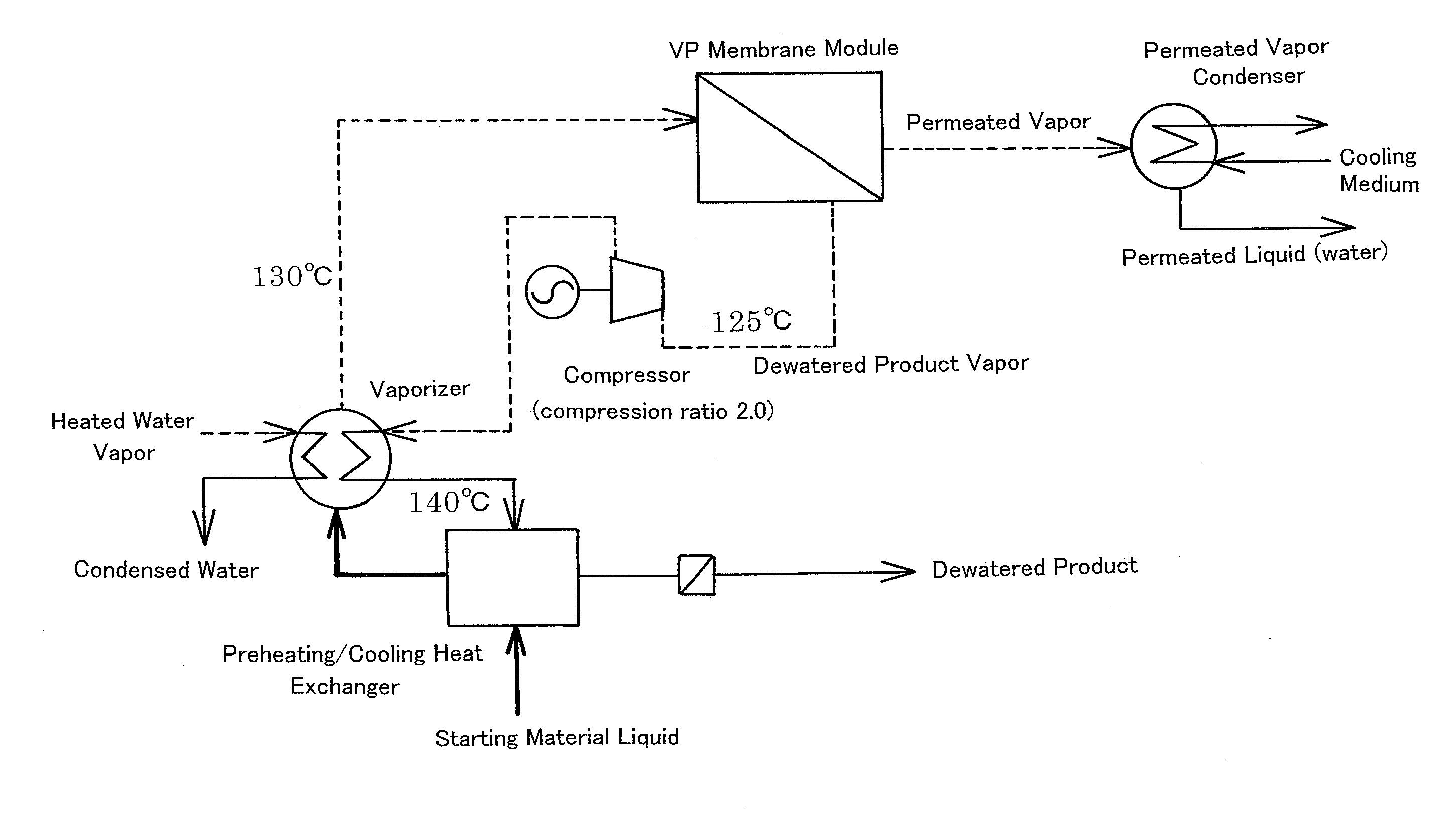
[0037]The vapor to go out of the membrane module is on a product grade as the composition thereof, however, the entire quantity of the vapor is fed into a compressor and pressurized more than the pressure of the vapor to go out of the vaporizer, thereby increasing the pressure of the vapor (consequently, the temperature of the pressurized vapor rises). The vapor to go out of the membrane module has an extremely low water content, and is a fluid that hardly causes corrosion and deterioration of the compression system.
[0038]The product vapor having been pressurized and heated in the compressor is used as the heat source for the vaporizer in place of ordinary heated water vapor. In the vaporizer, the pressurized product vapor is cooled by vaporization of the liquid starting material, thereby to be a dewatered product liquid.
[0039]It is desirable that the product liquid to be taken out of the system is, in general, immediately cooled to around room temperature for preventing vaporization, however, the heat can be used for preheating the liquid starting material.
[0040]For enhancing the efficiency of the invention, it is important that the power needed for compressor operation is minimized as much as possible relative to the constant quantity of latent heat of condensation to be recovered. Basically, it is the most important to design the compression ratio as small as possible.

Problems solved by technology

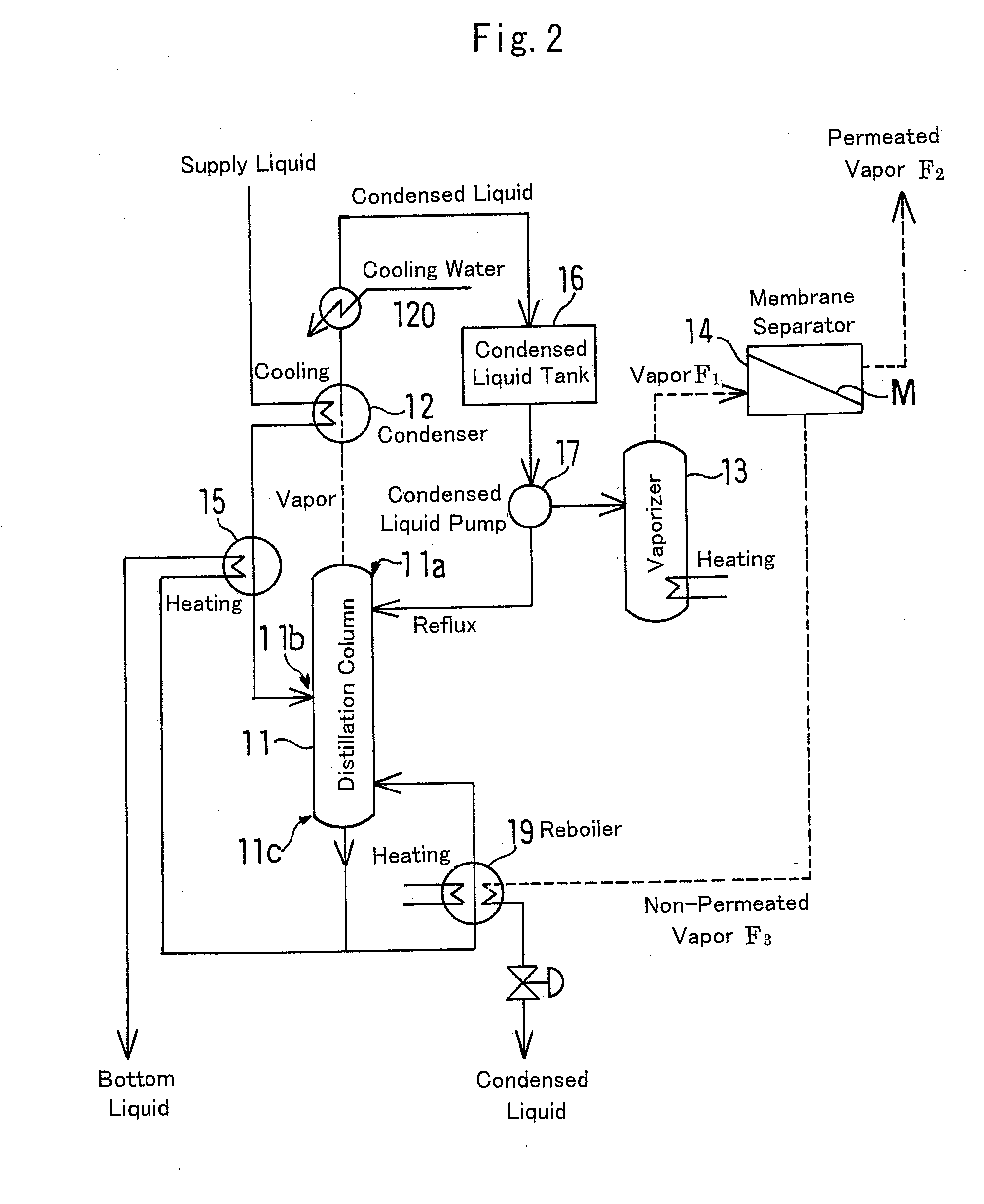
As described above, the latent heat of the product vapor must be recovered for the heat source of the reboiler at the bottom of the distillation column in order not to detract from the energy-saving merit, but the distillation column part and the VP part could not always be well balanced in point of the quantity of heat and, in addition, when the operation load fluctuates, the two would mutually affect each other, therefore causing a problem in the operation flexibility.
In case where the operation pressure in the distillation column is designed high, the system could be simple with high efficiency; but in case where a VP unit is arranged later in the distillation column designed for atmospheric pressure or reduced pressure (in vacuum), the pressure on the primary side of the VP unit must be atmospheric pressure or in vacuum, and as a result, the VP driving force may be small, a large membrane area may be necessary and sufficient dewatering could not be attained.
In case where water is removed to a high degree from a dilute aqueous solution of an organic substance such as ethanol produced through fermentation, and when the aqueous solution is directly fed and processed through membrane separation (especially VP), then the membrane area may be too large.

Method used


Image

  • Method for dewatering water-containing organic substance
  • Method for dewatering water-containing organic substance
  • Method for dewatering water-containing organic substance

Examples


example 1

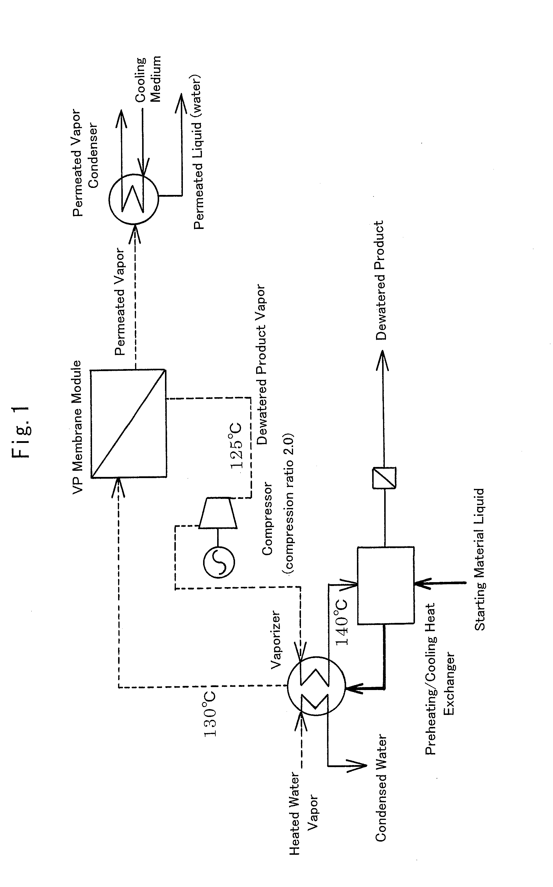
[0055]FIG. 1 shows the basic constitution (basic flow) of the invention. Some modification and change made by ordinary knowledge of those skilled in the art should not overstep the subject matter of the invention.

[0056]The liquid starting material, water-containing ethanol (having a concentration of 92.5 wt. % (95.0 vol. %) at a temperature of 30° C. and at a feed rate of 7,200 kg / h) is first introduced into a preheating / cooling heat exchanger, in which the dewatered ethanol liquid product (having a concentration of 99.7 wt. % (98.0 vol. %) at a yield of 6,600 kg / h (200 kL / day)) is cooled (the mean specific heat of the product liquid in cooling from a temperature 140 to 37° C. is 0.765 kcal / kg·° C.) and simultaneously the liquid starting material is preheated.

[0057]The liquid starting material is an aqueous ethanol solution having a concentration of 92.5 wt. % (95.0 vol. %), and the feed rate thereof is 7,200 kg / h. The mean specific heat in heating from a temperature 30 to 130° C. i...


PUM


Abstract

The present invention is to provide a VP dewatering method being applicable over a wide range, having good handling properties, and being economically efficient and highly energy-saving, which comprises compression-pressuring a dewatered vapor product to elevate a condensation temperature thereof and then re-using the same as a heat source for vaporizing a supply liquid. In dewatering a water-containing organic substance which is a liquid starting material according to a vapor permeation membrane separation method, a dewatered organic substance vapor discharged from a membrane module is pressurized with a compressor to elevate the condensation temperature of the vapor and then the vapor is fed to a vaporizer of said method to collect and use the latent heat of condensation thereof.

Description

TECHNICAL FIELD[0001]The present invention relates to a method for dewatering a water-containing organic substance. Typical examples of dewatering a water-containing organic substance include i) dewatering of bioethanol into ethanol for automobile fuel, ii) regeneration of high-purity organic solvent used in washing or draining and drying in a process for producing semiconductor or liquid crystal, iii) removal of water to be an impurity, which is contained in an organic liquid for use as a starting material for production of various chemical products and drug products, iv) removal of by-product water, which is produced through reaction such as typically esterification to accumulate in the product to thereby interfere with the completion of the reaction, etc. In that manner, there are an extremely large number of fields that require water removal or dewatering of a water-containing organic substance, and the present invention is effectively applicable to these fields.[0002]As a new e...

Claims


Application Information

Patent Timeline
IPC IPC(8): B01D61/36
CPCB01D53/22B01D71/028B01D2311/2673B01D2311/2669B01D2311/04B01D71/0281
Inventor FUJITA, SUGURUINOUE, SHIROTAKAKI, YOSHINOBU
Owner HITACHI ZOSEN CORP
Learn More