Systems and apparatus for seawater organics removal

a technology of organic removal and system, applied in the direction of sediment separation, vortex flow apparatus, sedimentation settling tank, etc., can solve the problems of deterioration of filtration efficiency, environmental pollution, and eventually the need to replace membranes, so as to accelerate aggregation and high throughput

Inactive Publication Date: 2012-06-21
PALO ALTO RES CENT INC
View PDF7 Cites 20 Cited by
  • Summary
  • Abstract
  • Description
  • Claims
  • Application Information

AI Technical Summary

Benefits of technology

[0030]The following co-pending and commonly assigned applications, naming Lean et al. as inventors, the disclosures of each being totally incorporated herein by reference, are mentioned: U.S. Published Application No. 2009 / 0050538, entitled, “Serpentine Structures for Continuous Flow Particle Separations”, by Lean et al.; U.S. Published Application No. 2008 / 0128331, entitled, “Particle Separation and Concentration System”, by Lean et al.; U.S. Published Application No. 2008 / 0230458, entitled, “Vortex Structure for High Throughput Continuous Flow Separation”, by Lean et al.; U.S. Published Application No. 2009 / 0114601, entitled, “Device and Method for Dynamic Processing in Water Purification”, by Lean et al.; U.S. Published Application No. 2009 / 0114607, entitled, “Fluidic Device and Method for Separation of Neutrally Buoyant Particles”, by Lean et al.; U.S. Published Application No. 2010 / 140092, entitled, “Flow De-Ionization Using Independently Controlled Voltages”, by Armin R. Volkel et al.; U.S. patent application Ser. No. 12 / 484,071, filed Jun. 12, 2009, entitled, “Method and Apparatus for Continuous Flow Membrane-Less Algae Dewatering”, by Lean et al.; U.S. Published Application No. 2009 / 0283455, entitled, “Fluidic Structures for Membrane-less Particle Separation”, by Lean et al.; U.S. Published Application No. 2009 / 0283452, entitled “Method and Apparatus for Splitting Fluid Flow in a Membrane-less Particle Separation System”, by Lean et al.; U.S. patent application Ser. No. 12 / 615,663, filed Nov. 10, 2009, entitled, “Desalination Using Supercritical Water and Spiral Separation”, by Lean et al.; U.S. Published Application No. 2010 / 0072142, entitled, “Method and System for Seeding with Mature Floc to Accelerate Aggregation in a Water Treatment Process”, by Lean et al.; U.S. patent application Ser. No. 12 / 484,038, filed Jun. 12, 2009, entitled, “Stand-Alone Integrated Water Treatment System for Distributed Water Supply to Small Communities”, by Lean et al.; U.S. patent application Ser. No. 12 / 484,005, filed Jun. 12, 2009, entitled, “Spiral Mixer for Floc Conditioning”, by Lean et al.; and U.S. patent application Ser. No. 12 / 484,058, filed Jun. 12, 2009, entitled, “Platform Technology for Industrial Separations”, by Lean et al.

Problems solved by technology

Biofouling causes severe problems to ships' hulls, coastal structures, industrial cooling towers and drinking water delivery systems.
This problem occurs when biological organisms naturally present in the fluid source are entrained in the fluid taken into a filtration system inlet or intake.
The build-up of a biofilm layer due to microbial growth, deposition of colloidal matter and adsorption of organics on reverse osmosis (RO), nanofiltration (NF) and ultrafiltration (UF) membrane surfaces leads to the deterioration of filtration efficiency and eventually the need to replace the membranes.
However, these solutions can prove costly, and at least in the case of chemical modification may result in the chemicals used being released into the raw water supply and upsetting the ecological balance.
Another problem for water and particularly seawater treatment systems is a seasonal event such as that known as “red tide”, which is an algae infestation, or a harmful algae bloom (HAB).
Other micro-organisms remove harmful or toxic matter from the habitat, resulting in the micro-organisms themselves becoming toxic.
Impingement of cellular material may lead to cell rupture, contamination of membranes, and dissemination of toxic cell material in the effluent waters.
However, the infestation may cover large areas and the suspension of filtration operations severely impacts the ability to provide filtered water, whether for industrial use or even for human consumption.
Processing fluid through the system is not only time consuming, but costly as the filtration devices become fouled and require cleaning or replacement, resulting in system shut down.

Method used


Image

  • Systems and apparatus for seawater organics removal
  • Systems and apparatus for seawater organics removal
  • Systems and apparatus for seawater organics removal

Examples


Embodiment Construction

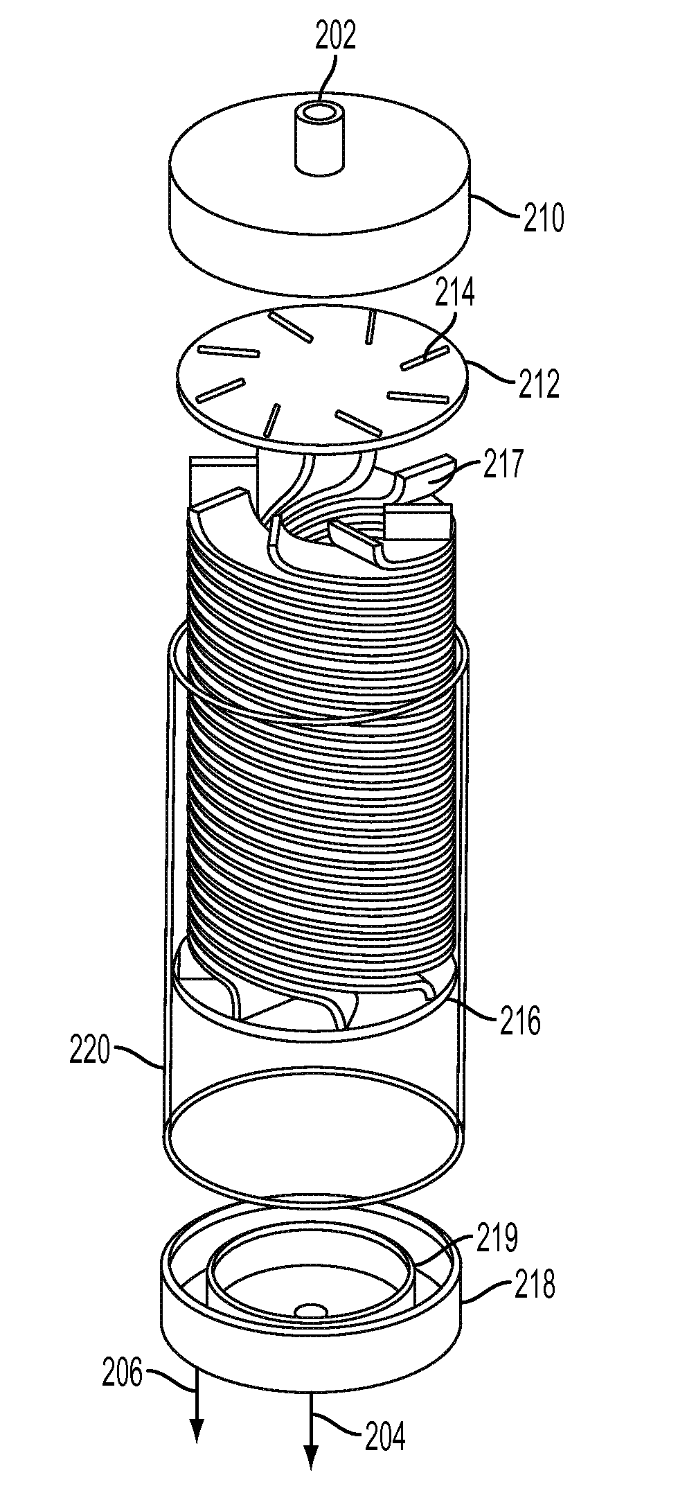
[0057]The presently described embodiments relate to various fluidic structures, implementations and selected fabrication techniques to realize construction of systems including membrane-less hydrodynamic pre-treatment separation units for the pre-treatment of raw seawater to remove bio-organic matter therefrom, and for returning the same, unruptured, to the raw seawater source without disturbing the ecological balance thereof. These contemplated systems provide for efficient input of fluid to be processed, and improved throughput. As used herein, the term “hydrodynamic pre-treatment separator” refers to the use of the hydrostatic force of the seawater environment, as well as gravitational force, to propel the seawater through the hydrodynamic pre-treatment separation system, including the hydrodynamic separator unit, without the need for using an external power source. However, this does not preclude the use of a pump for the device to operate.

[0058]It will be understood that variat...


PUM

PropertyMeasurementUnit
flow ratesaaaaaaaaaa
pressureaaaaaaaaaa
pressure dropaaaaaaaaaa

Abstract

A non-filtration pre-separation device and method for the removal of algae using the same, comprising a system having a hydrodynamic separator including at least one curved structure for the removal of bio-organisms from seawater, such structure having an inlet in operative connection with a source of raw seawater and a bifurcated outlet operative for passing pre-treated effluent fluid to a downstream filtration system and the removal of waste fluid. Various fluidic structures, implementations and selected fabrication techniques to realize such a device, whether singular or in stacked and/or packed parallel configuration are also provided.

Description

CROSS REFERENCE TO RELATED PATENTS AND APPLICATIONS[0001]The following co-pending and commonly assigned applications, the disclosures of each being totally incorporated herein by reference, are mentioned:[0002]U.S. Published Application No. 2009 / 0050538, entitled, “Serpentine Structures for Continuous Flow Particle Separations”, by Lean et al.;[0003]U.S. Published Application No. 2008 / 0128331, entitled, “Particle Separation and Concentration System”, by Lean et al.;[0004]U.S. Published Application No. 2008 / 0230458, entitled, “Vortex Structure for High Throughput Continuous Flow Separation”, by Lean et al.;[0005]U.S. Published Application No. 2009 / 0114601, entitled, “Device and Method for Dynamic Processing in Water Purification”, by Lean et al.;[0006]U.S. Published Application No. 2009 / 0114607, entitled, “Fluidic Device and Method for Separation of Neutrally Buoyant Particles”, by Lean et al.;[0007]U.S. Published Application No. 2010 / 140092, entitled, “Flow De-ionization Using Indep...

Claims


Application Information

Patent Timeline
Patent Type & Authority Applications(United States)
IPC IPC(8): C02F1/38C02F1/00C02F1/52
CPCB01D21/0087B01D61/145B01D21/34B01D61/04B01D61/10B01D2311/04B01D2311/2642B01D2311/2649B01D2311/2661C02F1/38C02F1/5236C02F1/56C02F9/00C02F2103/08C02F2103/44B01D61/025B01D61/027B01D21/265B01D21/0003
Inventor LEAN, MENG H.ZUBACK, JOECHANG, NORINE E.KOLE, ASHUTOSHMELDE, KAISEO, JEONGGI
Owner PALO ALTO RES CENT INC
Why Eureka
Try Eureka