Weld Overlay Structure and a Method of Providing a Weld Overlay Structure

a technology of overlay structure and weld, which is applied in the direction of manufacturing tools, corrosion diminishing boiler components, light and heating apparatus, etc., can solve the problems of high heat flux of heat transfer tubes and membrane surfaces, insufficient resistance of base materials to high temperature corrosion, and particulate erosion/corrosion attack

Inactive Publication Date: 2012-08-23
POURIN WELDING ENG +1
View PDF42 Cites 27 Cited by
  • Summary
  • Abstract
  • Description
  • Claims
  • Application Information

AI Technical Summary

Benefits of technology

[0017]An object of the present invention is to provide a method of providing a weld overlay structure on a h

Problems solved by technology

Heat transfer tubes and membrane surfaces are often subject to a high heat flux, as well as high temperature corrosion and particulate erosion/corrosion attack.
The base materials, in many cases, do not provide adequate resistance to high temperature corrosion attack from, for example, combustion products in a power boiler or from a hot exhaust flue gas stream in a waste heat recovery boiler.
In RDF and black liquor recovery boilers, the heat fluxes and temperatures are typically lower, but corrosive conditions exist based on the fuel chemistry.
Due to, for example, the reasons mentioned above, wastage rates of heat transfer tubes and membrane surfaces can be significant, up to 2.5 mm/year or more, and can rapidly lead to a forced outage of the boiler.
In addition, the metallization technique involves thickness limits, beyond which temperature differences between the base material and the metal spray, as well as mechanical bond defects, can also lead to spalling.
In other words, penetration of the weld metal into the base material and the

Method used


Image

  • Weld Overlay Structure and a Method of Providing a Weld Overlay Structure
  • Weld Overlay Structure and a Method of Providing a Weld Overlay Structure
  • Weld Overlay Structure and a Method of Providing a Weld Overlay Structure

Examples


Embodiment Construction

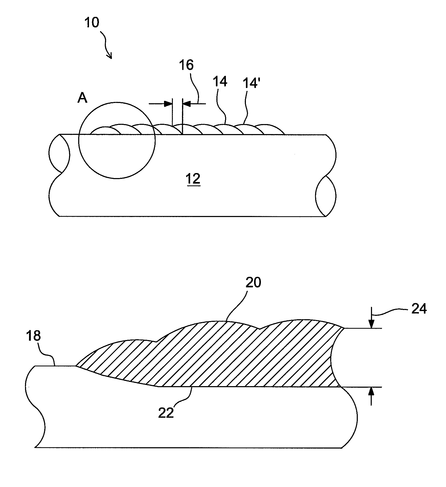
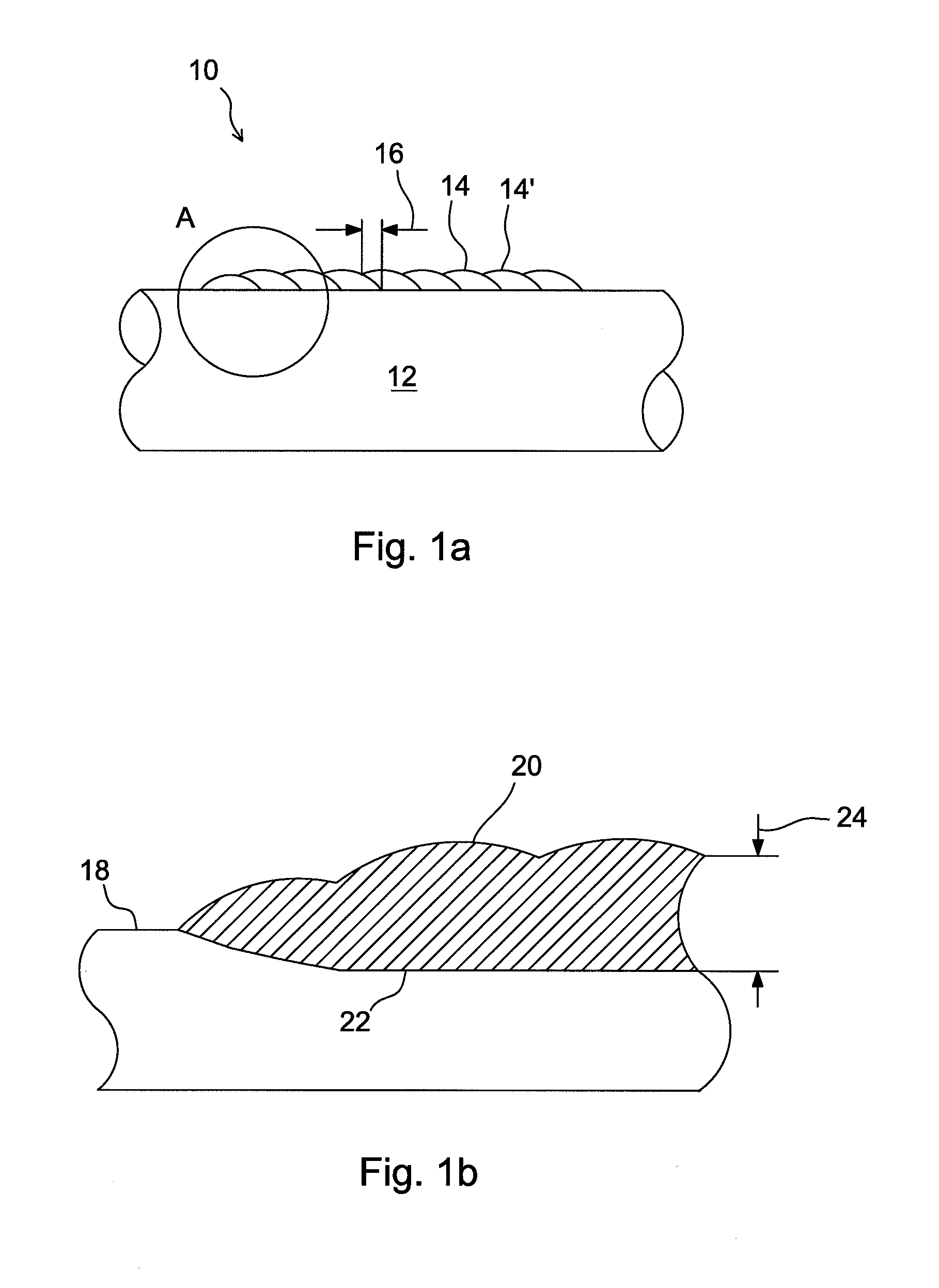
[0033]FIG. 1a shows a schematic cross section of a conventional spiral weld overlay 10, or a 360 degrees weld overlay, on a heat transfer tube 12. The weld overlay is formed by applying a continuous weld bead as a spiral on the outer surface of the tube. Conventionally, the successive circles 14, 14′ of the spiral have a relatively large overlap 16, typically, about 30% to about 50% or from about 6 mm to about 10 mm.

[0034]FIG. 1b shows a schematic enlarged view of the detail A of FIG. 1a. FIG. 1b shows, in addition to the original outer surface 18 of the tube and the outer surface 20 of the formed weld overlay, also the fusion line 22, i.e., the inner surface of the layer that is formed by the welding. The fusion line extends inside the original tube, because the base metal tube material is partially melted and mixed with the high alloy weld material.

[0035]As is shown in FIGS. 1a and 1b, in a conventional weld overlay method is created a cladding, which has a relatively coarse as-we...


PUM

PropertyMeasurementUnit
Fractionaaaaaaaaaa
Fractionaaaaaaaaaa
Lengthaaaaaaaaaa

Abstract

A method of providing a weld overlay structure on a heat transfer tube or a membrane surface. A first continuous bead portion of an overlay material is applied onto the heat transfer tube or membrane surface by using a weld head to melt the overlay material. A second continuous bead portion of the overlay material is applied onto the heat transfer tube or membrane surface by using a weld head to melt the overlay material, in which the second bead portion partially overlaps with the first bead portion, forming a groove between the first bead portion and the second bead portion. A third continuous bead portion of an overlay material is applied onto the heat transfer tube or membrane surface by using a weld head to melt the overlay material into the groove between the first bead portion and the second bead portion, so as to form a relatively smooth surface.

Description

BACKGROUND OF THE INVENTION[0001]1. Field of the Invention[0002]The present invention relates to a weld overlay structure and a method of providing a weld overlay structure on a heat transfer tube or a membrane surface. The invention relates especially to a weld overlay structure and a method of providing a weld overlay structure on a heat transfer tube or a membrane surface which is in, or is to be used in, a boiler, but it may also be applied to chemical process vessels or in maritime applications.[0003]2. Description of the Related Art[0004]A conventional membrane surface, or a waterwall, made of parallel tubes connected together by metal strips, so-called fins, to construct a wall forming, for example, an enclosure of a furnace, is a typical example of heat transfer surfaces of a power boiler. High pressure water flows inside the tubes to extract heat from high temperature combustion gases on the outer surface of the tubes. Water tubes and membrane surfaces in different boilers,...

Claims


Application Information

Patent Timeline
IPC IPC(8): B32B15/01B32B3/00B23K9/04
CPCB23K9/048B23K2201/14Y10T428/12451F22B37/025Y10T428/12333F22B37/108B23K2101/14B33Y30/00
Inventor MURPHY, JOHNLEE, HAISHENG
Owner POURIN WELDING ENG
Why Eureka
Try Eureka