
Ultraviolet fiber laser system

a fiber laser and ultra-violet technology, applied in the field of fiber lasers, can solve the problems of high ongoing cost of ownership, poor beam quality of high-power excimer lasers, and use of high-voltage electronics, so as to reduce laser volume, improve laser efficiency, and limit laser beam quality

Inactive Publication Date: 2013-02-21
VERALAS
View PDF3 Cites 52 Cited by
  • Summary
  • Abstract
  • Description
  • Claims
  • Application Information

AI Technical Summary

Benefits of technology

This patent describes new laser systems that use fiber laser technology and special crystalline materials to emit light in the UV and visible ranges. These systems have high pulse energy, power, and can control the duration and repetition rate of the pulses. This technology can replace traditional excimer lasers. The invention also involves a hybrid fiber-bulk master oscillator-power amplifier system, which allows for higher power and better control of pulse width and duration. Overall, this patent offers an improved solution for laser technology that is more efficient, compact, and cost-effective.

Problems solved by technology

Presently, these applications primarily use excimer gas lasers because of the lack of other suitable laser sources.
While being reliable laser sources, excimer lasers are bulky, require periodic service and, therefore, can have high ongoing costs of ownership.
In addition high power excimer lasers often exhibit poor beam quality, use high voltage electronics and have low wall plug efficiency.
However, obtaining the desired average power level and pulse energy for nanosecond pulses in the higher harmonic spectral emissions has been a problem.
However, even for transform limited operation, the ultra short pulse fiber lasers have relatively broad spectral line widths (this is a basic quantum mechanics uncertainty principle).
This broad spectral bandwidth limits efficient nonlinear frequency conversion to higher optical harmonics.
In addition increasing the ultra-short laser pulse energy significantly increases the already high peak power which, in turn, triggers the detrimental nonlinear optical effects that impact the fiber laser power scaling.
Thus, power and pulse energy scaling of a fiber laser is a challenging task, particularly when applications require close to diffraction limited beam quality, a pulse width less than 10 ns, tens of watts of average power, and a polarized beam.
Scaling a fiber laser pulse energy in the visible and UV spectral range through nonlinear frequency conversion is likewise limited by the low available pulse energy of the fundamental wavelength.
While fiber bundling can increase the pulse energy in the fundamental beam and high order harmonics, combining the outputs from bundled individual fiber lasers deteriorates the resulting laser beam and requires fine (nanosecond or sub-nanosecond) gating of the individual laser pulses to overlap.
Additionally, the polarizations of the beams have to be aligned for efficient nonlinear harmonic generation which complicates spatial alignment of the individual fiber laser sources in the bundle.
However, this approach also requires several individual fiber laser sources, and is bulky, complicated and costly.
However, this still requires two laser systems which need to be synchronized, properly triggered, and spatially overlapped in nonlinear crystals.

Method used


Image

  • Ultraviolet fiber laser system
  • Ultraviolet fiber laser system
  • Ultraviolet fiber laser system

Examples


second embodiment

[0059]FIG. 4 illustrates a laser system in accordance with the invention that effectively energy scales a 980 nm seed laser 410 by Yd-doped fiber amplifiers. The output of laser 410 may be connected, in series, to a fiber coupled isolator 412 (in addition any optical isolator that may be incorporated into the package of the fiber couple diode laser, i.e., between the diode laser chip and the optical fiber), an acoustic-optical modulator (AOM) 414 which produces optical pulses through intensity modulation, a core or cladding pumped fiber amplifier / pre-amplifier 416 to amplify low power pulses created by AOM 414 to the energy level close to the gain saturation of the booster amplifier 463, a band pass filter 418, and a second isolator 420 to a PM signal and pump combiner 422 (WDM or fused). The DC un-doped fiber of the PM pump and signal combiner 422 may be connected to a DC LMA Yb-doped double clad PM gain fiber 424 having an appropriately chosen length so that it may be coiled and h...

third embodiment

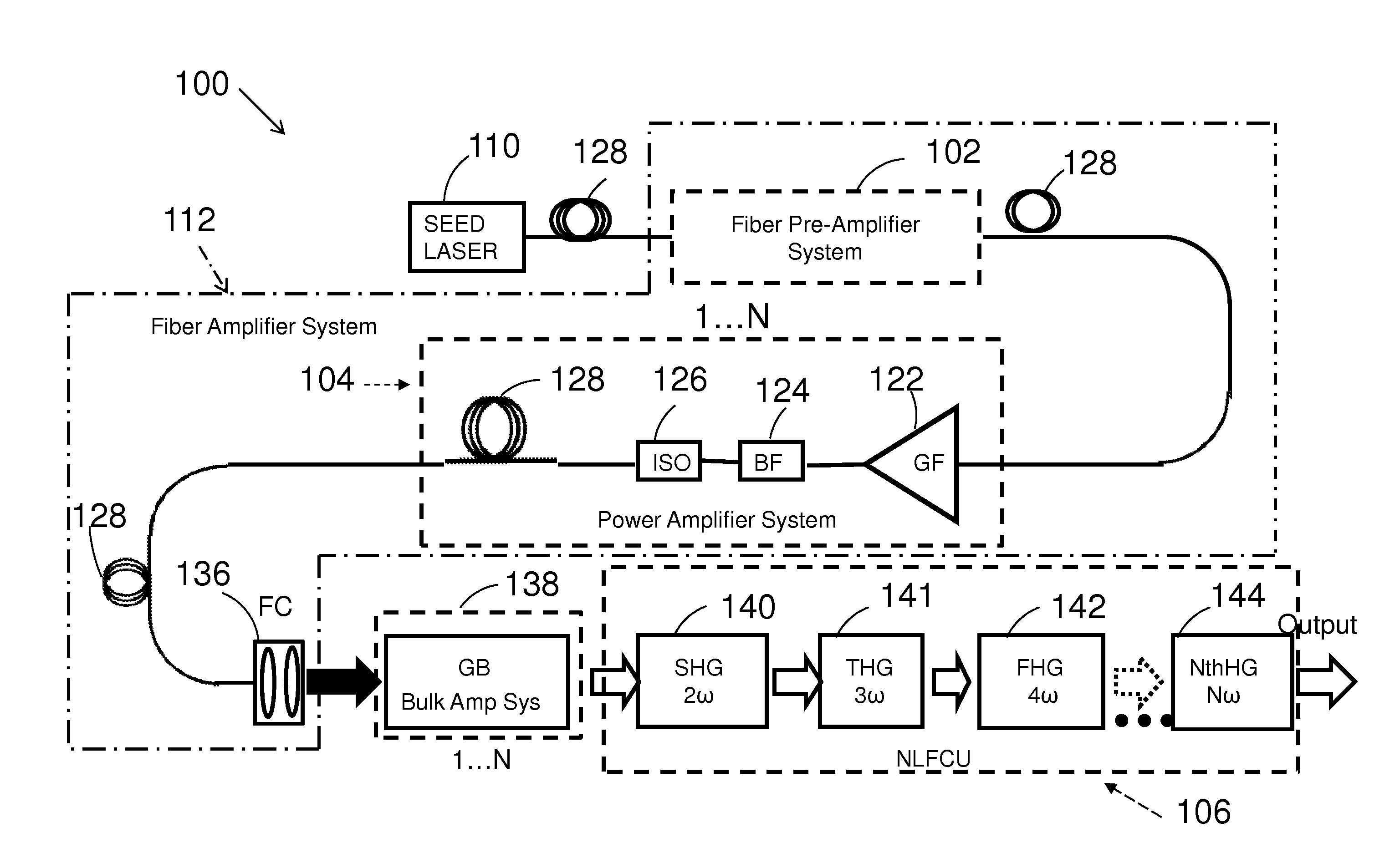
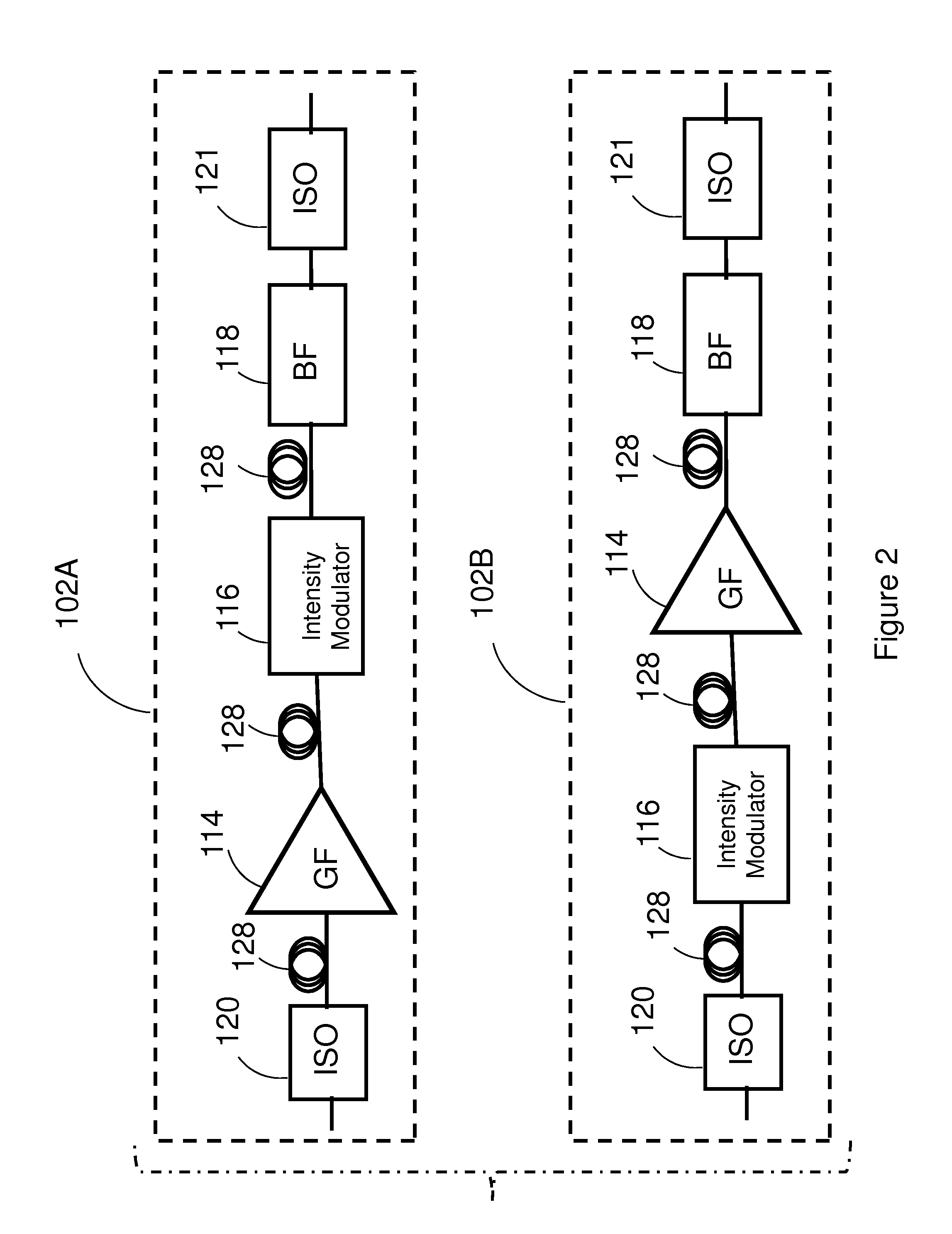
[0063]FIG. 5 illustrates the invention in which a DFB, 100 mW, PM fiber coupled diode laser 510 operating at 981 nm wavelength is used as a CW seed laser for the master oscillator. The 981 nm laser output may be supplied, in series, to an isolator 512, an amplifier / pre-amplifier 514, and an intensity modulator 520 which may comprise a PM fiber coupled small chirp or chirp-free electro-optical Mach-Zhender modulator producing 1ns pulses at a 1000 Hz pulse repetition rate (PRR) (i.e., a duty cycle of 0.000001). With a 4 dB insertion loss, about 40 nW of the 981 nm light average output power may be obtained from the Mach-Zhender modulator 520. The output from the intensity modulator may be applied to a band pass filter 522, an isolator 524, and to a single or multi stage Yb3+-doped fiber booster amplifier 530. Elements 532, 534, 536 and 538 may be similar to elements 122, 124, 126 and 128 previously described in connection with FIG. 1. A core-pumped or a cladding pumped Yb-doped fiber ...

fourth embodiment

[0066]In fourth embodiment the invention affords pulse and CW operation of Er fiber lasers based on LMA, DC Er3+-doped gain fibers optically cladding pumped either resonantly into a 1530 nm absorption band or a 976 nm absorption band of Er3+. The gain band of Er3+-doped fibers spans from approximately 1530 nm to over 1600 nm. The approach described above for Yb-doped fiber laser may also be used for laser power scaling with close to diffraction limited laser beam quality when an Er3+-doped LMA fiber is used (with appropriate selection of MO wavelength and spectral properties of all other system components, appropriate for an Er3+ fiber laser). This enables pulse and CW laser operation at virtually any laser line in the 1530-1610 nm spectral range as well as for red and UV operation of these lasers via nonlinear frequency conversion to higher harmonics of their fundamental frequencies.

[0067]FIG. 6 illustrates the fourth embodiment of the invention that has an overall configuration si...


PUM


Abstract

Laser master oscillator—power amplifier system for generating high pulse energy, high average power laser pulses in the ultraviolet 191.25-201.25 nm and 243-246.25 nm spectral ranges, and in the visible 450-537.5 nm spectral range with controllable pulse duration and pulse repetition rate employ a master oscillator seed laser operating in the infra-red spectral range, and a single series connected chain of hybrid fiber—bulk crystalline amplifiers coupled to a non-linear frequency conversion unit to convert the laser pulses to the ultraviolet and visible spectral ranges.

Description

CROSS REFERENCE TO RELATED APPLICATIONS [0001]This application claims the benefit of U.S. Application No. 61 / 524,884 filed Aug. 18, 2011, and U.S. Application No. 61 / 524,436 filed Aug. 17, 2011.BACKGROUND OF THE INVENTION[0002]The invention relates generally to lasers and laser systems, and more particularly to fiber lasers operating in the ultraviolet (UV) spectral range.[0003]Ultraviolet laser sources having high power and high pulse energy for short nanosecond pulse widths are required for many important applications such as laser material processing and medicine, e.g., eye surgery. Presently, these applications primarily use excimer gas lasers because of the lack of other suitable laser sources. Excimer lasers can produce laser emissions at several main wavelengths, such as nanometer (nm) wavelengths of 351 nm, 308 nm, 248 nm, 193 nm and 157 nm. While being reliable laser sources, excimer lasers are bulky, require periodic service and, therefore, can have high ongoing costs of o...

Claims


Application Information

Patent Timeline
Patent Type & Authority Applications(United States)
IPC IPC(8): H01S3/30
CPCH01S3/06758H01S3/09415H01S3/1616H01S3/1618H01S3/1671H01S3/2316H01S3/1675H01S3/0078H01S3/0085H01S3/0092H01S3/1625H01S3/1636H01S3/0064H01S3/2375
Inventor TER-MIKIRTYCHEV, VALERI V.
Owner VERALAS
Learn More