Manufacturing method of grating

a manufacturing method and grating technology, applied in the field of grating manufacturing methods, can solve the problem of difficult to make a quartz grating with high efficiency

Active Publication Date: 2013-05-02
TSINGHUA UNIV +1
View PDF6 Cites 20 Cited by
  • Summary
  • Abstract
  • Description
  • Claims
  • Application Information

AI Technical Summary

Problems solved by technology

It is difficult to make a quartz grating with high density, sub-wavelength, and mark-space ratio.

Method used


Image

  • Manufacturing method of grating
  • Manufacturing method of grating
  • Manufacturing method of grating

Examples


Embodiment Construction

[0014]Reference will now be made to the drawings to describe various inventive embodiments of the present disclosure in detail, wherein like numerals refer to like elements throughout.

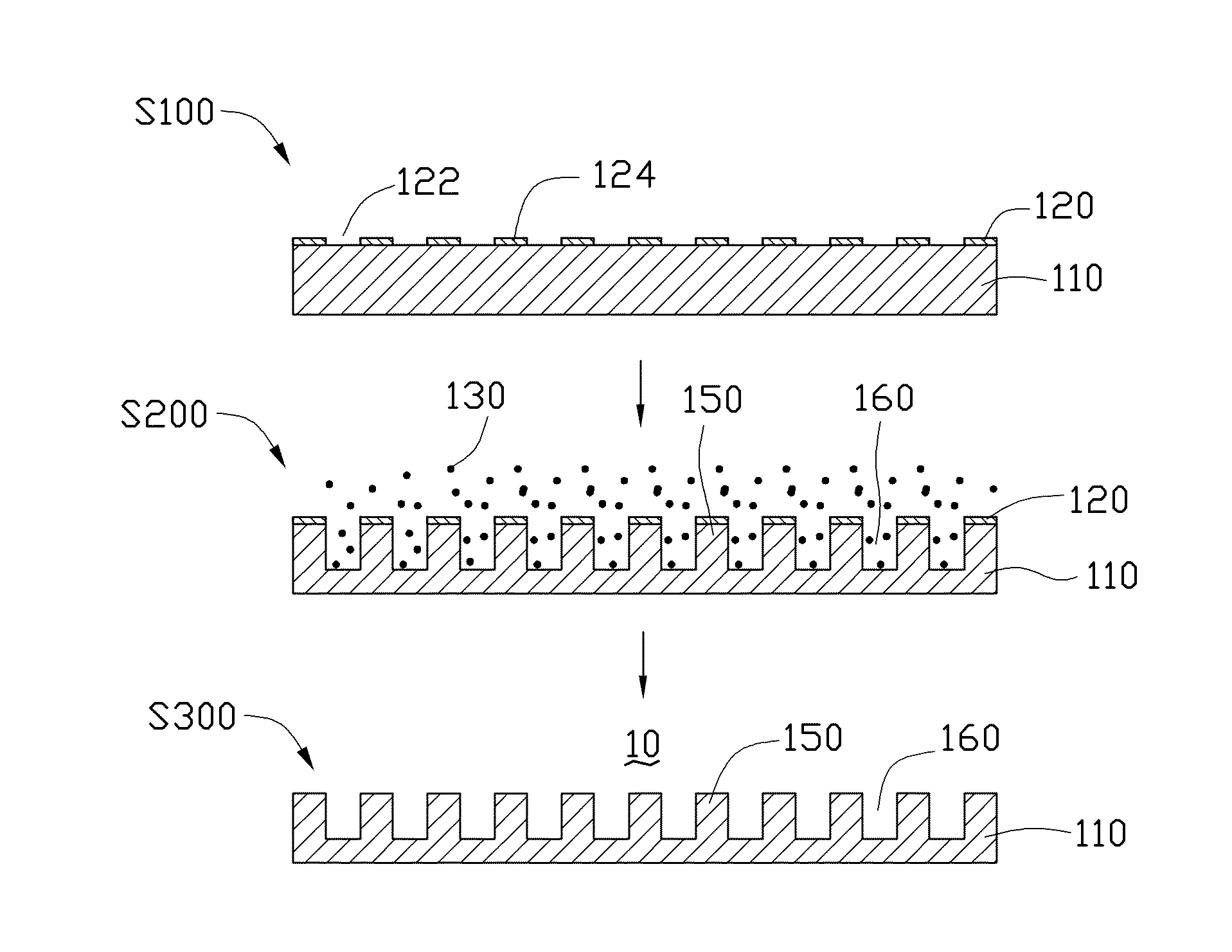
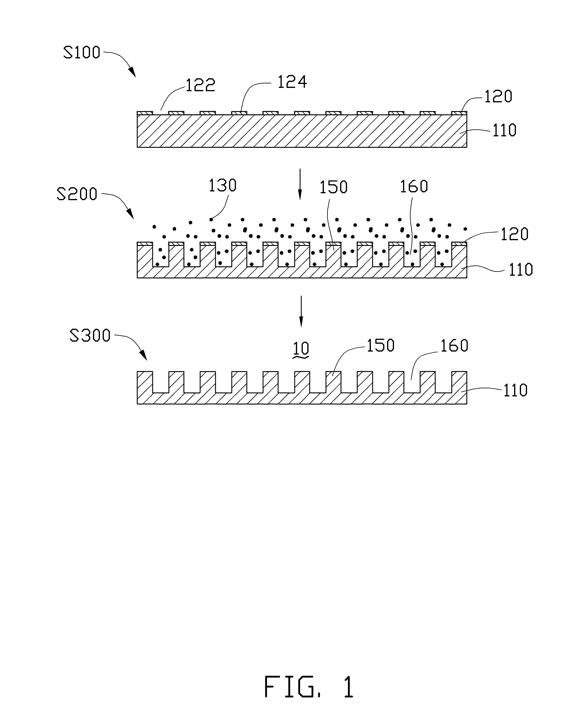
[0015]Referring to FIG. 1, one embodiment of a manufacturing method of a grating 10 includes the following steps. The grating 10 can be a sub-wavelength grating.

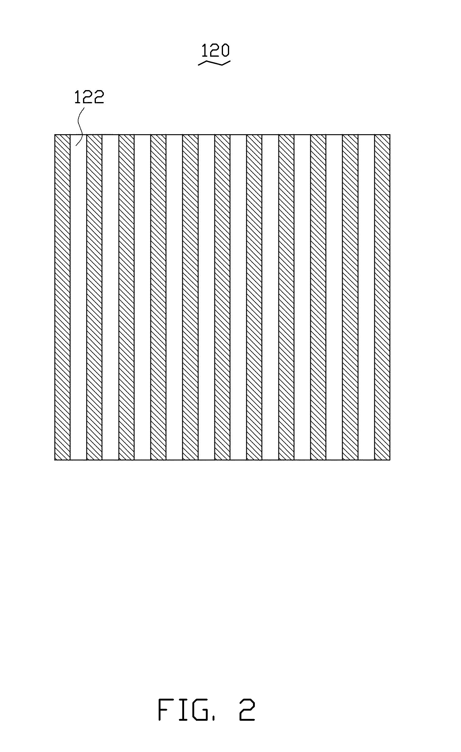
[0016]In step S100, a substrate 110 is provided, and a patterned mask layer 120 is formed on a surface of the substrate 110.

[0017]The substrate 110 can be a circular plate, a square plate, or any other shape plate. The substrate 110 may be a semiconductor substrate or a silicon substrate. The material of the substrate 110 may be gallium nitride (GaN), gallium arsenide (GaAs), sapphire, aluminum oxide, magnesium oxide, silicon, silica, silicon nitride, or silicon carbide, wherein the silica may form a quartz substrate or a glass substrate. In the embodiment, the substrate 110 is a quartz substrate.

[0018]In addition, the patterned mask layer 120,...


PUM

PropertyMeasurementUnit
poweraaaaaaaaaa
poweraaaaaaaaaa
pressureaaaaaaaaaa

Abstract

The disclosure relates to a method for making a grating. The method includes the following steps. First, a substrate is provided. Second, a photoresist film is formed on a surface of the substrate. Third, a nano-pattern is formed on the photoresist film by nano-imprint lithography. Fourth, the photoresist film is etched to form a patterned photoresist layer. Fifth, a mask layer is covered on the patterned photoresist layer and the surface of the substrate exposed to the patterned photoresist layer. Sixth, the patterned photoresist layer and the mask layer thereon are removed to form a patterned mask layer. Seventh, the substrate is etched through the patterned mask layer by reactive ion etching, wherein etching gases includes carbon tetrafluoride (CF4), sulfur hexafluoride (SF6) and argon (Ar2). Finally, the patterned mask layer is removed.

Description

BACKGROUND[0001]1. Technical Field[0002]The disclosure relates to a manufacturing method of a grating.[0003]2. Description of Related Art[0004]A sub-wavelength grating is a common optical component in the semiconductor industry. The size of the sub-wavelength grating is similar to or less than the active wavelength of the sub-wavelength grating. It is difficult to make a quartz grating with high density, sub-wavelength, and mark-space ratio. The sub-wavelength grating may be made by electron beam lithography, focused ion beam lithography, deep-ultraviolet lithography, holographic lithography, and nano-imprint lithography.[0005]In the prior art, the aspect ratio of the sub-wavelength grating is 1:1 so as to limit the application field.BRIEF DESCRIPTION OF THE DRAWINGS[0006]The parts in the drawings are not necessarily drawn to scale, the emphasis instead being placed upon clearly illustrating the principles of at least one embodiment. In the drawings, like reference numerals designat...

Claims


Application Information

Patent Timeline
Patent Type & Authority Applications(United States)
IPC IPC(8): B44C1/22H05H1/24
CPCG02B5/1809G02B5/1857G03F7/095B82Y40/00H01L33/508B82Y10/00G03F7/0002G02B5/18G03F7/70691
Inventor ZHU, ZHEN-DONGLI, QUN-QINGZHANG, LI-HUICHEN, MO
Owner TSINGHUA UNIV
Why Eureka
Try Eureka