Method for Manufacturing Resonant Tube, Resonant Tube and Cavity Filter

Active Publication Date: 2013-05-23
SHENZHEN TATFOOK NETWORK TECH
View PDF3 Cites 1 Cited by
  • Summary
  • Abstract
  • Description
  • Claims
  • Application Information

AI Technical Summary

Benefits of technology

[0021]Furthermore, the methods for manufacturing a resonant pole proposed in the present invention produce a resonant pole, which has desired hardness, t

Problems solved by technology

Upon researches and practices on the prior art, the inventor of the present invention observed the fact that the resonant pole for use in a microwave RF device is more complicated in shape and requires higher accuracy in the manufacture, making the preparation and mechanical processing of a resonant pole with invar steel ingot more costly (higher consumption of raw materials) and limiting the manufacturing efficiency.
Moreover, invar steel prepared using a melt casting

Method used


Image

  • Method for Manufacturing Resonant Tube, Resonant Tube and Cavity Filter
  • Method for Manufacturing Resonant Tube, Resonant Tube and Cavity Filter
  • Method for Manufacturing Resonant Tube, Resonant Tube and Cavity Filter

Examples


embodiment i

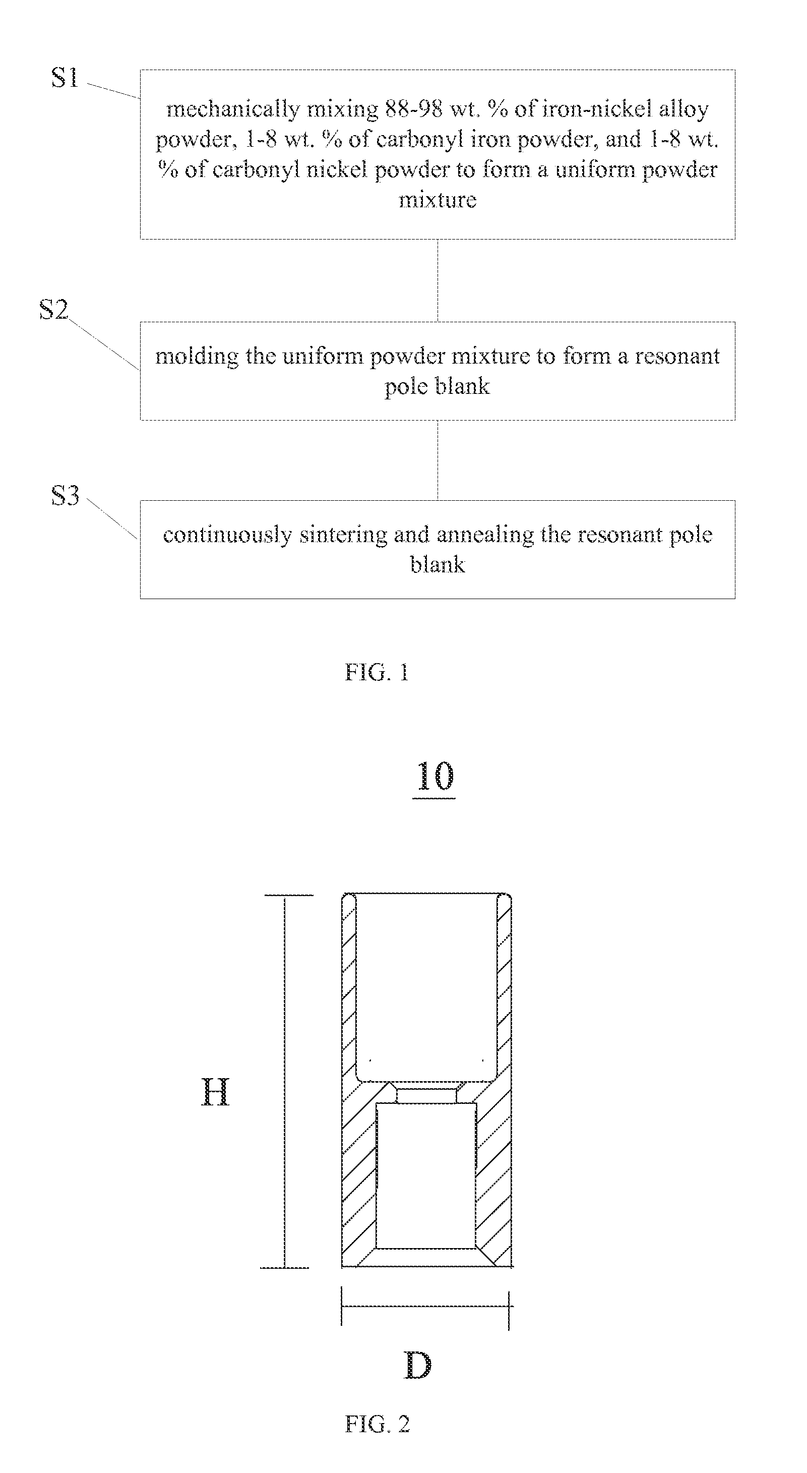
[0035]A method for manufacturing a resonant pole as shown in FIG. 1 is provided, which comprises:

[0036]Step S1: Mechanically Mixing 88-98 wt. % of Iron-Nickel Alloy Powder, 1-8 wt. % of Carbonyl Iron Powder, and 1-8 wt. % of Carbonyl Nickel Powder to Form a Uniform Powder Mixture;

[0037]In this embodiment, the iron-nickel alloy powder is preferably 92-96 wt. %; the carbonyl iron powder is preferably 2-4 wt. %; and the carbonyl nickel powder is preferably 2-4 wt. %. In the most preferred aspect, the iron-nickel alloy powder is 94 wt. %; the carbonyl iron powder is 3 wt. %; and the carbonyl nickel powder is 3 wt. %. It bears mentioning that these raw materials inevitably comprise a small amount of impurities, including carbon, nitrogen, sulfur and phosphor, which generally are not more than 0.1%.

[0038]In this embodiment, the iron-nickel alloy powder, the carbonyl iron powder, and the carbonyl nickel powder are uniformly and mechanically mixed with a stearic acid lubricant which takes u...

application embodiment 1

[0057]88% of high purity iron-nickel alloy powder, 6% of carbonyl iron powder, 6% of carbonyl nickel powder, which are prepared using powder metallurgical technology, and a stearic acid lubricant occupying 1-2% of the total weight of the aforesaid powders, are press molded in one step. The press molded product is then subjected to a continuous sintering process (under the highest temperature of 1450° C. for 10 hours) and an annealing process under the reducing atmosphere of H2 (under the temperature of 1150° C. for 12 hours). Thereafter, an electroplating process is carried out to obtain an iron-nickel resonant pole having an outer diameter of 10.0 mm, and a highness of 11.8 mm. It is observed from testing that the corresponding cavity filter with a single cavity has a resonant frequency up to 2900 MHz, and a temperature drift lower than 0.32 MHz.

embodiment ii

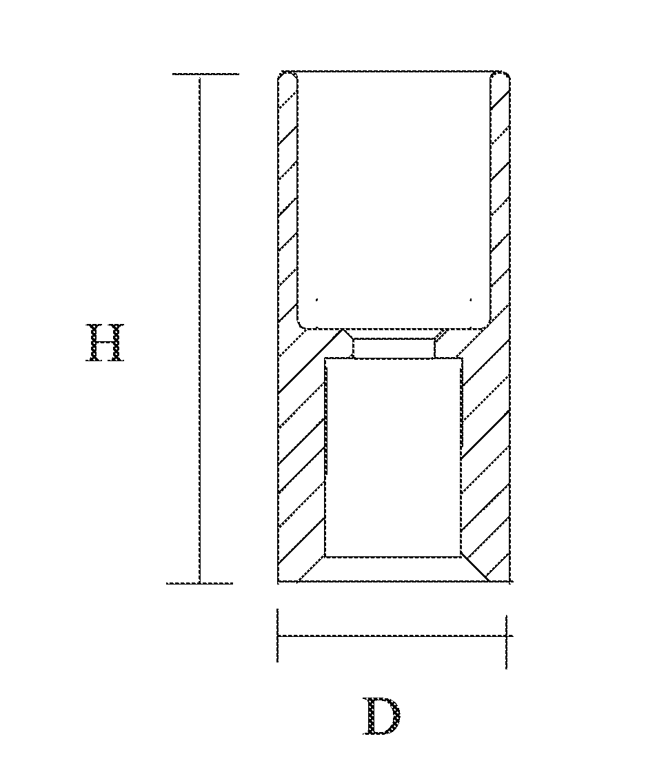
[0058]A resonant pole 10 having a structure as shown in FIG. 2 is provided in this embodiment, which has a highness of H and an outer diameter of D. Resonant pole 10 comprises 88-98 wt. % of iron-nickel alloy, 1-8 wt. % of carbonyl iron, and 1-8 wt. % of carbonyl nickel.

[0059]In this embodiment, the iron-nickel alloy, the carbonyl iron, and the carbonyl nickel are press molded or injection molded to form a resonant pole.

[0060]The resonant pole prepared from the iron-nickel alloy, the carbonyl iron, and the carbonyl nickel mixed in the aforesaid ratios using one-step molding significantly reduces consumption of raw materials and the cost in mechanical processing.

[0061]In this embodiment, preferably, the iron-nickel alloy is of 92-96 wt. %, the carbonyl iron of 2-4 wt. %, and the carbonyl nickel of 2-4 wt. %. In the most preferred embodiment, the iron-nickel alloy is of 94 wt. %, the carbonyl iron of 3 wt. %, and the carbonyl nickel of 3 wt. %.

[0062]According to a further embodiment o...


PUM

PropertyMeasurementUnit
Temperatureaaaaaaaaaa

Abstract

A method for manufacturing a resonant tube is provided in the present invention, which comprises: mechanically mixing 88-98 wt. % of iron-nickel alloy powder, 1-8 wt. % of carbonyl iron powder, and 1-8 wt. % of carbonyl nickel powder to form a uniform powder mixture; molding the uniform powder mixture to form a resonant tube blank; and continuously sintering and annealing the resonant tube blank. Also provided in the present invention are a resonant tube and a cavity filter. The method for manufacturing a resonant tube provided in the present invention significantly enhances production efficiency while greatly reducing consumption of raw materials. Moreover, the resonant tube provided in the present invention reduces, to the greatest extent, segregation of alloy components and coarse and uneven microstructures, thereby increasing the performance and stability of the corresponding products.

Description

TECHNICAL FIELD[0001]The present invention relates to the field of microwave communication, and particularly relates to a resonant pole and a method for manufacturing the resonant pole, and further relates to a cavity filter using the resonant pole.BACKGROUND TECHNOLOGY[0002]As a passive filter, the cavity filter has excellent anti-interference performance such that it is widely used in, for example, the field of mobile communications. A cavity filter comprises a cavity body and a cover plate, wherein the cavity body comprises a plurality of cavities, each accommodating a resonant pole. Therefore, a cavity filter includes a plurality of resonant poles.[0003]The resonant pole is irreplaceable in the cavity filter, and forms a key component that affects the performance of the cavity filter. That is why strict requirements need to be satisfied when manufacturing and processing a resonant pole.[0004]Conventionally, invar steel is used as a raw material for making a resonant pole. Invar ...

Claims


Application Information

Patent Timeline
IPC IPC(8): H01P11/00H01P7/06
CPCC22C33/0285H01P11/002B22F5/106B22F2998/10B22F2999/00H01P11/008H01P7/06B22F3/02B22F3/10B22F2003/248B22F2201/013
Inventor ZHAO, KELUNSHEN, FENGPINGWAN, BINGBINGZHOU, YANZHAO
Owner SHENZHEN TATFOOK NETWORK TECH
Why Eureka
Try Eureka