Method of preparing sandwich composite coating on engineering plastic surface

Inactive Publication Date: 2013-06-20
XIAMEN RUNNER IND CORP
View PDF4 Cites 7 Cited by
  • Summary
  • Abstract
  • Description
  • Claims
  • Application Information

AI Technical Summary

Benefits of technology

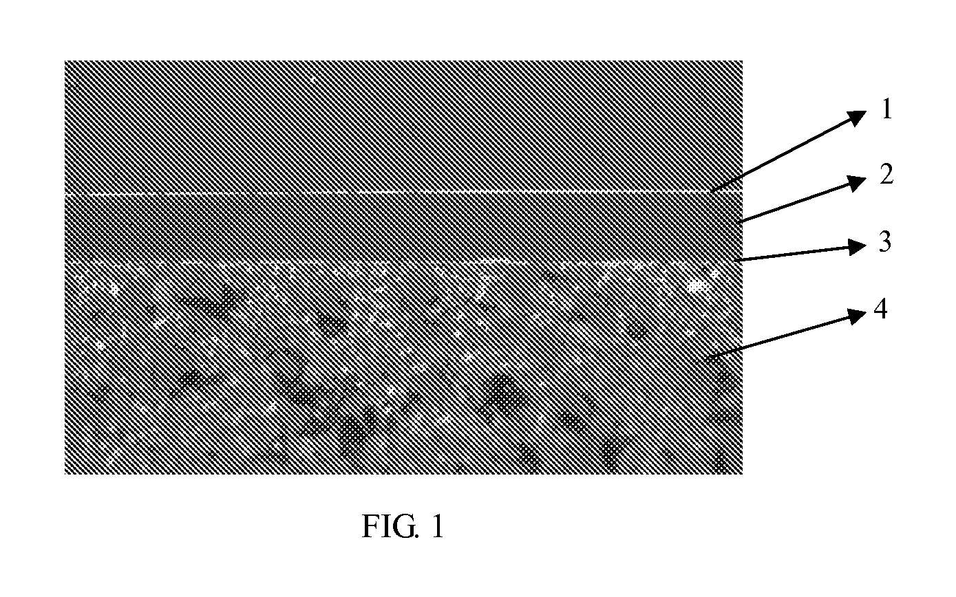
[0026]Since the coating of the present invention includes two metal layers, and an organic coating included between the two metal layers, the coating of the invention is called a sandwich composite coating, wherein the organic coating is provided for leveling the surface of the blank and covering defects formed on the surface of the blank to improve the luster of the product. Therefore, the present invention can be used to substitute the conventional wet electroplating method.
[0027]Tests show that the metalized engineering plastic product produced in accordance with the present invention not only has the advantages of being corrosion resistant, abrasion resistant, weather resistant, temperature resistant and ability to be multiple colors, but also provides a hard s

Problems solved by technology

However, the wet plating technology has the following drawbacks: (1) consuming much water and power and producing a large quantity of wastewater; (2) using toxic chemical electrolytes and additives; (3) discharging toxic waste gases; (4) consuming a large quantity of metal; (5) using hexavalent chromium which is harmful to human health; and (6) requiring a high-standard substrate surface, and providing a limited scope of applicability.
Obviously, this prior art causing tremendous environmental pollutions and hazards requires improvements.
A surface treatment method applicable for metals and non-metals was disclosed in P.R.C. Pat. No. CN1468976, this patented technology overcomes the serious environmental pollution problem of the conventional surface treatment method, but the products so produced have the drawbacks of poor corrosion resistance and low surface luster.
However, the dry coating technology still has the following problems and drawbacks:1. Most of the rising and degreasing procedures still require the use of chemicals and discharge wastewater.2. Defects such as spots, precipitates, greases, air bubbles, protrusions and recess

Method used


Image

  • Method of preparing sandwich composite coating on engineering plastic surface
  • Method of preparing sandwich composite coating on engineering plastic surface

Examples


Example

[0030]In the first preferred embodiment, a chromium plated PC / ABS mirror casing is provided for the illustration of the present invention.

[0031](1) A blank is formed by injecting PC / ABS for the injection molding, and sent into a physical vapor deposition (PVD) furnace and rinsed and activated by a plasma source glow (provided that the current is 0.3 A, the bias voltage is 100V, the flow of argon is 30 SCCM, the flow of oxygen is 20 SCCM, the vacuum pressure inside the furnace is 0.1 Pa, and the activation time is 5 min).

[0032](2) The arc target in the PVD furnace is turned on, chromium is plated on a surface of a PC / ABS blank (provided that the current of the target source is 60 A, the bias voltage is 100V, the flow of argon is 50 SCCM, the vacuum pressure inside the furnace is 0.1 Pa, and the chromium plating time is 12 min).

[0033](3) After the metal basal film is plated with chromium, the surface of the blank is activated by plasma (provided that the current of the ion source is 0...


PUM

PropertyMeasurementUnit
Temperatureaaaaaaaaaa
Lengthaaaaaaaaaa

Abstract

A method of preparing a sandwich composite coating on an engineering plastic surface is provided to enhance the functions and quality of a plastic coated metal product, lowers the production cost, saves water (without requiring any water in the whole manufacturing process). The method includes the steps of dry cleaning and activating a plastic blank, placing the activated plastic blank into a PVD furnace, forming a metal basal film on the activated plastic blank, performing a plasma activation of the plastic blank with the metal basal film, sputtering an organic coating, and forming a metal coated film layer on the plastic blank placed into PVD furnace to produce a metalized engineering plastic product which is applicable for sanitary ware, electronics, electric appliances and in the automobile industry.

Description

BACKGROUND OF THE INVENTION[0001]1. Field of the Invention[0002]The present invention relates to a method of forming a metal composite layer on an engineering plastic surface, in particular to a full-dry method of preparing a sandwich composite coating on an engineering plastic surface.[0003]2. Description of Related Art[0004]Products featuring high corrosion, abrasion resistance, flat mirror-surface and decoration can be produced by wet plating a plastic surface, and plastic metallization (plated Cu / Ni / Cr metal film) has been used extensively for a long time. However, the wet plating technology has the following drawbacks: (1) consuming much water and power and producing a large quantity of wastewater; (2) using toxic chemical electrolytes and additives; (3) discharging toxic waste gases; (4) consuming a large quantity of metal; (5) using hexavalent chromium which is harmful to human health; and (6) requiring a high-standard substrate surface, and providing a limited scope of appli...

Claims


Application Information

Patent Timeline
IPC IPC(8): C23C14/02C23C14/34
CPCB05D1/02B05D1/12B05D3/0209B05D3/0263B05D3/067C23C14/12B05D5/067B05D7/02B05D2350/65B05D2401/32C23C14/025B05D3/141
Inventor WU, ZI-BAOLEE, MIN-ZEN
Owner XIAMEN RUNNER IND CORP
Why Eureka
Try Eureka