Composite wall panel with low thermal conductivity and sufficient strength for structural use

a technology of composite wall panels and structural use, applied in the field of composite wall panel systems, can solve the problems of easy cracks in both foamed concrete and foamed concrete, less practical than directly reducing the overall thermal conductivity (k) of the envelope of buildings, and severely degrade the transport properties and carbonation resistance of foamed concrete. good thermal insulation properties, good barrier resistan

Active Publication Date: 2013-08-22
NANO & ADVANCED MATERIALS INST
View PDF6 Cites 47 Cited by
  • Summary
  • Abstract
  • Description
  • Claims
  • Application Information

AI Technical Summary

Benefits of technology

[0011]In the second aspect of the present invention, the FRCC layer is formed of different components comprising cement, sand, water, fiber, lightweight filler, fly ash, silica fume, slag, superplasticizer and HPMC. Various composite designs are possible for making this layer. The thickness of each FRCC layer is between 5-50 mm; the density of FRCC layer is about 1000-1800 kg / m3. The at least two FRCC layers serve as protective layers with good barrier resistance to moisture / chloride ion / gas and good thermal insulation property.

Problems solved by technology

However, it is less practical than directly reducing the overall thermal conductivity (k) of the envelopes of buildings.
However, in practice, due to the low toughness of foamed concrete, it is easy for cracks to form in both foamed concrete and its protective coating / surface treatment (if applied) under loading.
While the formation of fine cracks should not affect structural performance (as the tensile load capacity of concrete is neglected anyways), it can severely degrade the transport properties and carbonation resistance of foamed concrete (Chandra & Berntsson, 2003).
Experimental findings in those studies actually indicated severe steel rusting at the vicinity of cracks in foamed concrete.
However, both the thermal conductivity and transport properties of the lightweight FRCC are not disclosed.

Method used


Image

  • Composite wall panel with low thermal conductivity and sufficient strength for structural use
  • Composite wall panel with low thermal conductivity and sufficient strength for structural use
  • Composite wall panel with low thermal conductivity and sufficient strength for structural use

Examples


example 1

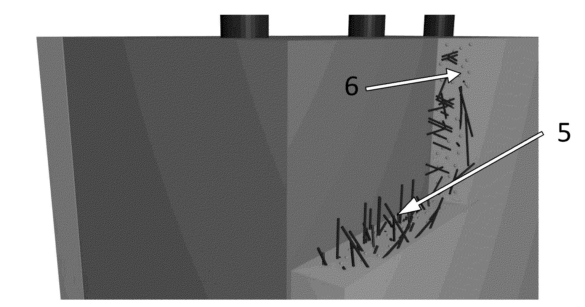
[0032]The thermal insulation property of foamed concrete is illustrated in this example. FIG. 4 shows the setup including a normal concrete 7, a foamed concrete 8, a FRCC layer 9 on both normal concrete 7 and foamed concrete 8 surfaces, an infrared lamp 10 and a thermocouple meter 11. The specimen size of the normal concrete 7 and foamed concrete 8 is 300 mm (length)×200 mm (width)×100 mm (depth). The density of normal concrete 7 and foamed concrete 8 are about 2400 kg / m3 and 1300 kg / m3 respectively. Since the present invention is a composite wall panel comprised of foamed concrete core and one or more FRCC layers, a FRCC layer 9 is cast on foamed concrete 8. To have a fair comparison, the same FRCC layer 9 is also cast on a normal concrete 7 with the same thickness. The infrared lamp 10 is used to simulate the situation where external wall is exposed to sunlight. With the infrared lamp 10 continuously shining on the FRCC layers 9 (for 2 hours in this example), the temperature of th...

example 2

[0035]For the composite wall panel of the present invention to serve as precast external wall, sufficient structural strength is required. Compared to ordinary foamed concrete which can only provide compressive strength of less than 15 MPa, the foamed concrete of the presently disclosed composite wall panel can provide 4-70 MPa compressive strength depending on the composition design of the concrete core, as shown in our experimental results. The composition design of the foamed concrete core is shown in Table 2. With different designs of composition, the density and compressive strength of the foamed concrete core are adjusted. The trend of 28-day compressive strength against plastic density of foamed concrete is shown in FIG. 5. From the results, the foamed concrete of the present invention with plastic density higher than 1400 kg / m3 can provide 28-day compressive strength higher than 25 MPa. For the foamed concrete with plastic density 1600 kg / m3, a 28-day compressive strength of...

example 3

[0037]This example serves to illustrate the concerned properties of the fiber reinforced cementitious composite (FRCC) used for preparing the protective layer of the present invention.

[0038]The FRCC composite used for the protective layer preparation comprises cement, fly ash, water, lightweight filler, silica sand, discontinuous polyvinyl alcohol (PVA) fiber, superplasticizer and Hydroxypropyl Methyl Cellulose (HPMC). The examples of different proportions of the components in the composite, expressed as parts by weight, unless otherwise indicated, are tabulated as follows:

TABLE 3LightweightFiberMix No.CementFly ashWaterSandfillerHPMCSP(vol. %)1100.350.1650.0650.00110.0151.7520.670.330.350.1650.060.00110.0081.7530.50.50.350.1650.0650.00110.0071.7540.20.80.350.1650.050.00110.0071.75where SP = superplasticizer

[0039]The cement used is Type I Portland cement (BS 12:1996, 52.5N) from Green Island Cement Co. Limited, Hong Kong. The fly ash is supplied by the CLP Holdings Limited, Hong Kon...


PUM

PropertyMeasurementUnit
compressive strengthaaaaaaaaaa
plastic densityaaaaaaaaaa
mean lengthaaaaaaaaaa

Abstract

The present invention provides a composite wall panel with good thermal insulation and sufficient strength for structural use which is designed for the fabrication of energy efficient building. The composite wall panel of the present invention comprises a foamed concrete core with sufficient compressive strength and low thermal conductivity which is sandwiched between two lightweight ductile fiber reinforced cementitious composite (FRCC) protective layers with low thermal conductivity, good barrier resistance to moisture/chloride ion/gas, multiple cracking as well as certain amount of steel reinforcements. These composite wall panels are useful in a variety of buildings in both cold and hot regions.

Description

CROSS-REFERENCE TO RELATED APPLICATION[0001]This application claims benefits from the U.S. provisional patent application No. 61 / 633,920 filed Feb. 21, 2012, and the disclosure of which is incorporated herein by reference.FIELD OF THE INVENTION[0002]The present invention relates to a composite wall panel system with sufficient strength for structural use and low thermal conductivity, and a method for fabricating the system.TECHNICAL BACKGROUND OF THE INVENTION[0003]With increasing concerns of the greenhouse gas emission arising from electricity consumption and the rising energy cost, the demand for better thermal insulation in the building enclosures has drastically increased over the past few years. To improve the thermal insulation of building envelope, increasing the wall thickness is one of the solutions. However, it is less practical than directly reducing the overall thermal conductivity (k) of the envelopes of buildings.[0004]For a given wall thickness, the thermal insulation...

Claims


Application Information

Patent Timeline
Patent Type & Authority Applications(United States)
IPC IPC(8): C04B26/00E04B2/00B32B13/02E04B2/84B32B5/18B32B7/02
CPCC04B28/02C04B38/10C04B2111/00612C04B2201/20C04B2201/32C04B2201/50C04B26/00B32B5/18B32B7/02B32B13/02E04B2/847E04B2/00E04C2/049B32B13/045B32B2250/40B32B2266/04B32B2307/304B32B2307/50B32B2307/7246C04B38/106Y10T428/24967C04B14/06C04B16/0633C04B18/08C04B18/141C04B18/146C04B20/002C04B24/14C04B24/226C04B40/0028C04B16/0641C04B24/2641C04B14/42C04B2103/32C04B14/386C04B14/24C04B24/383E04B1/80E04C5/073Y10T428/249968Y02W30/91B32B2266/049
Inventor LEUNG, CHRISTOPHER KIN YINGCHEUNG, KWOK FAIZHU, HONGGANGLIN, SZE WAI
Owner NANO & ADVANCED MATERIALS INST
Why Eureka
Try Eureka