
Use of porous membrane and composite membrane thereof in redox flow energy storage battery

a technology of porous membranes and energy storage batteries, which is applied in the direction of sustainable manufacturing/processing, cell components, indirect fuel cells, etc., can solve the problems of limiting the commercialization of vfb, low ion selectivity, and high cost of nafion® membranes, so as to avoid the low chemical stability, enhance the membrane vanadium/proton selectivity and ion conductivity, and enhance the membrane vanadium/proton

Active Publication Date: 2013-09-26
DALIAN INST OF CHEM PHYSICS CHINESE ACAD OF SCI +1
View PDF2 Cites 42 Cited by
  • Summary
  • Abstract
  • Description
  • Claims
  • Application Information

AI Technical Summary

Benefits of technology

The patent presents a new type of porous membrane and composite membrane for use in redox flow batteries, particularly for vanadium flow batteries. These membranes are made of high molecular weight resin and have a unique structure that allows for the isolation of vanadium ions while still allowing protons to pass through. The membranes are prepared using a phase inversion method and can have a controlled pore size and thickness. The membranes can be doped with inorganic particles and can also have ion exchange groups grafted onto their surface. The technical effects of this patent include improved performance and efficiency of redox flow batteries using these membranes and composites.

Problems solved by technology

However, Nafion® membranes suffer from their extremely high cost, especially exhibit the disadvantage like low ion selectivity etc. when used for the VFB, which limits their further commercialization of VFB.
Because these membranes containing fluorosulfonic showed some problems such as low ion selectivity on vanadium ions and high cost, considerable effort had been gone into the development and characterization of non-fluorosulfonic ion exchange membrane, including sulfonated polyaryletherketone, polyether sulphone and polyether sulphone etc.
For the most non-fluorosulfonic ion exchange membrane, the induction of ion exchange groups can dramatically lower the chemical stability, which limits the life-time of membrane in VFB.

Method used


Image

  • Use of porous membrane and composite membrane thereof in redox flow energy storage battery
  • Use of porous membrane and composite membrane thereof in redox flow energy storage battery
  • Use of porous membrane and composite membrane thereof in redox flow energy storage battery

Examples


example 1

[0058]7.5 g PAN was dissolved in 50 mL DMSO and kept stirring for 5 h to form the polymer solution. The polymer solution was cast on a glass plate, immediately immersed into 5 L water and solidified for 5 min to form the porous membrane with the thickness of 500 μm.

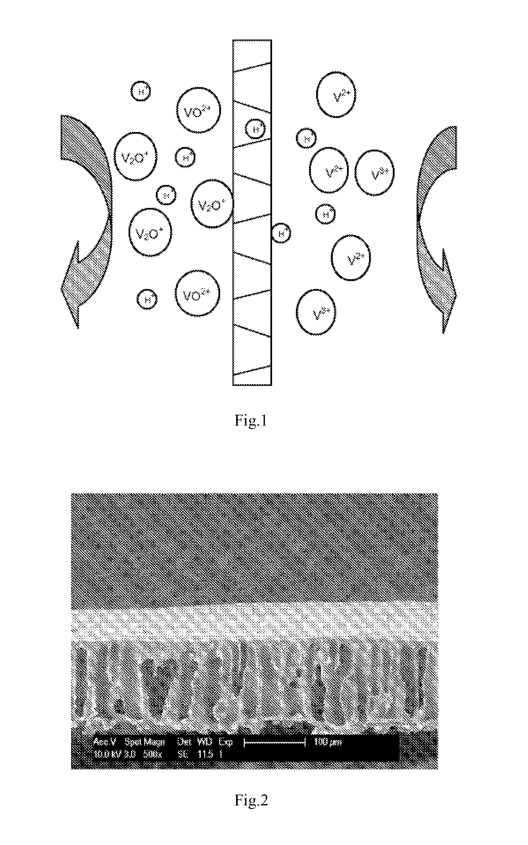
[0059]The cross-section morphology of the prepared membrane showed uniformly porous structure, as given in FIG. 2. The membrane was fabricated in a VRB single cell with carbon felt electrodes and graphite current collectors. The concentrations of vanadium ions and H2SO4 in the electrolyte solution were 3 M. The efficient area of the membrane was 9 cm2 and the testing current density was 80 mA cm2. The coulombic efficiency (CE), voltage efficiency (VE) and energy efficiency (EE) were 66.1%, 81.1% and 53.6%, respectively.

example 2

[0060]7.5 g PAN was dissolved in the mixed solvent consisting of 30 mL DMSO and 20 mL THF and kept stirred for 5 h to form the polymer solution. The polymer solution was cast on a glass plate. After evaporation for 10 s, the plate was immediately immersed into 5 L water and solidified for 10 min to form the porous membrane with the thickness of 500 μm.

[0061]The membrane was fabricated in a VRB single cell with carbon felt electrodes and graphite current collectors. The efficient area of the membrane was 9 cm2 and the testing current density was 80 mA cm−2. The concentrations of vanadium ions and H2SO4 in the electrolyte solution were 1.5 M and 3 M respectively. The coulombic efficiency (CE), voltage efficiency (VE) and energy efficiency (EE) were 80.7%, 82.1% and 66.2%, respectively.

example 3

[0062]7.5 g PAN was dissolved in the mixed solvent consisting of 30 mL DMSO and 20 mL THF and kept stirred for 5 h to form the polymer solution. The polymer solution was cast on a glass plate. After evaporation for 20 s, the plate was immediately immersed into 5 L water and solidified for 10 min to form the porous membrane with the thickness of 500 μm.

[0063]The membrane was fabricated in a VRB single cell with carbon felt electrodes and graphite current collectors. The efficient area of the membrane was 9 cm2 and the testing current density was 80 mA cm−2. The concentrations of vanadium ions and H2SO4 in the electrolyte solution were 1.5 M and 3 M respectively. The coulombic efficiency (CE), voltage efficiency (VE) and energy efficiency (EE) were 91.8%, 81.5% and 75%, respectively.

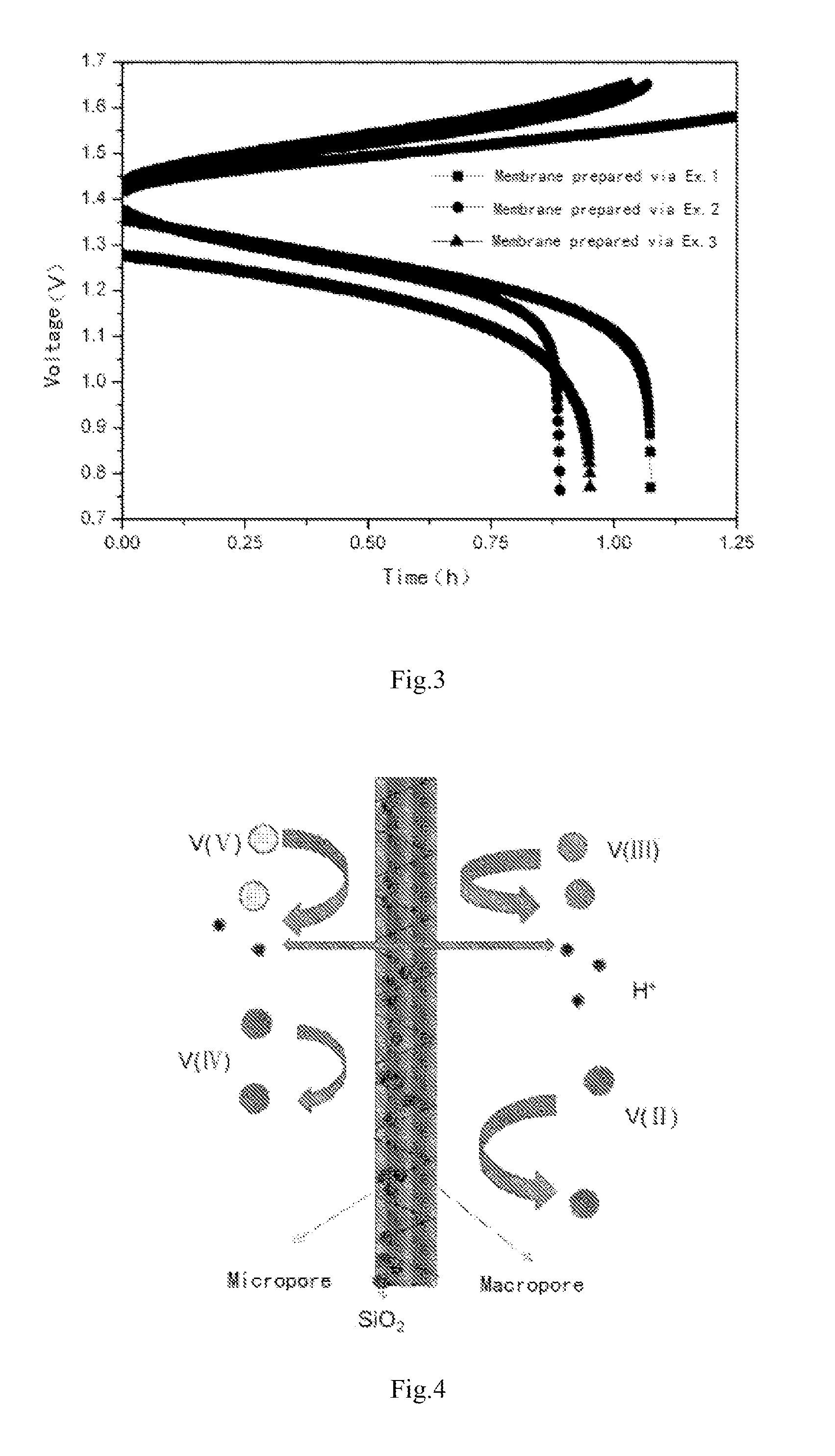
[0064]Seen from the single cell performance of Example 1, 2 and 3 given in FIG. 3, as the pore size of membrane decreases, the CE increases, the EE keep the same value and hence the EE also increases. Thus...


PUM

PropertyMeasurementUnit
thicknessaaaaaaaaaa
porosityaaaaaaaaaa
thicknessaaaaaaaaaa

Abstract

Disclosed is use of a porous membrane and a composite membrane thereof in a redox flow batteries, and in particular the use thereof in a vanadium redox flow battery. The membrane can effectively realize the separation of ions with different valence states, and an ion transfer without any ion exchange group. The pore size and structure of the porous membrane can be controlled by filling an inorganic substance or grafting an ion exchange group in the pore, in order to improve the barrier properties of the porous membrane for vanadium ions and to increase proton conductivity.

Description

FIELD OF THE INVENTION[0001]The invention relates to one type of porous membranes and their composites for redox flow battery application, in particular for vanadium flow battery application.BACKGROUND OF THE INVENTION[0002]Redox flow battery being a new electrochemical energy storage technology exhibits high energy conversion efficiency, flexible design, high energy storage capacity, flexible location, deep discharge, high safety, environmental friendly and low maintenance cost compared with other energy storage techniques. A number of applications have been considered, such as renewable energy storage for wind energy, solar energy etc., Emergency Power Supply, Standby Power System, peaking shaving as well as load leveling. Vanadium flow battery (VFB) has been considered as one of the most compelling electrochemical energy storage techniques due to its features like high safety, good stability, high efficiency, life longer than 15 years and low cost.[0003]A membrane / separator, bein...

Claims


Application Information

Patent Timeline
Patent Type & Authority Applications(United States)
IPC IPC(8): H01M8/02H01M8/20H01M8/18
CPCC08J5/22H01M8/1018H01M8/1067H01M8/1088H01M8/20C08J2327/16Y02E60/528H01M8/0293H01M8/188C08J5/2293Y02E60/521Y02E60/50Y02P70/50
Inventor ZHANG, HUAMINLI, XIANFENGZHANG, HONGZHANGSHI, DINGQIN
Owner DALIAN INST OF CHEM PHYSICS CHINESE ACAD OF SCI
Learn More