
Compound semiconductor structure

a semiconductor compound and compound technology, applied in the field of semiconductor structure, can solve the problems of poor interface between the semiconductor compound and the dielectric, the inability to employ standard cmos techniques, and the direct relationship between the poor interface and the degraded device performance, so as to reduce the capacitance of the gate capacitance, the effect of avoiding contamination of the sample and/or oxidation of the substra

Inactive Publication Date: 2014-02-06
IBM CORP
View PDF5 Cites 11 Cited by
  • Summary
  • Abstract
  • Description
  • Claims
  • Application Information

AI Technical Summary

Benefits of technology

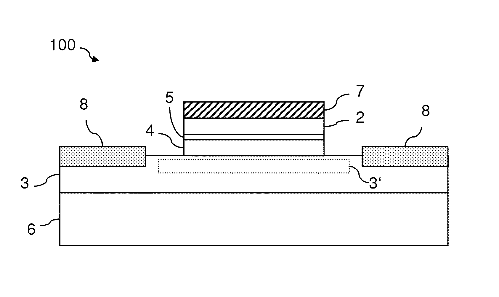
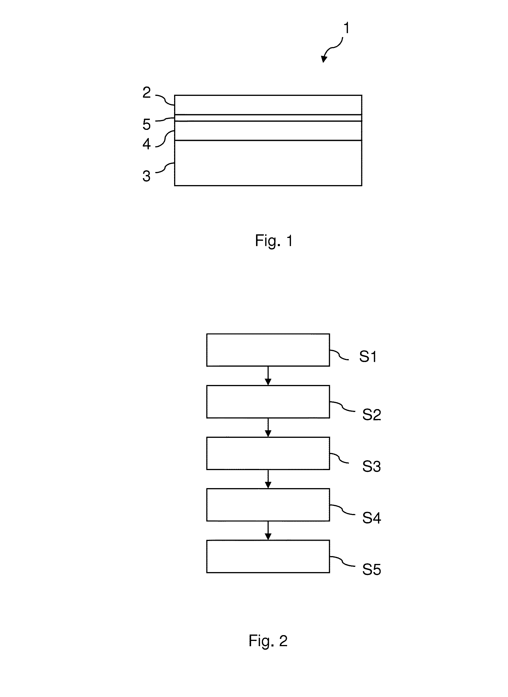
The patent proposes a semiconductor structure with a barrier layer between the dielectric layer and the passivation layer to prevent chemical reactions between the two layers. This barrier layer can help to reduce the formation of silicate and increase the capacitance of the structure, while also allowing for thin Si layers to effectively passivate the surface of the compound semiconductor material. This configuration may also reduce the diffusion of oxygen to the interface of the Si passivating layer with the compound semiconductor, which can potentially lower the interface state densities.

Problems solved by technology

GaAs being a promising alternative semiconductor material, however, does not have a natural oxide so that standard CMOS techniques cannot be employed.
Direct deposition of high-k dielectrics on GaAs or compounds semiconductors usually results in unpassivated surfaces with a high density of undesired interface traps and, hence, a poor interface between the semiconductor compound and the dielectric.
Such a poor interface is directly related to degraded device performances.

Method used


Image

  • Compound semiconductor structure
  • Compound semiconductor structure
  • Compound semiconductor structure

Examples


examples

[0079]FIG. 9A shows graphs depicting spectroscopic data of embodiments of semiconductor structures. In FIG. 9B the investigated structures a depicted. The graphs in FIG. 9A correspond to X-ray photoelectron spectroscopy data. The columns show Ga3p, Si2p, Al2p and Hf5p core level spectra as a function of the binding energy each. The vertical lines L1, L2, L3 indicate a shift of the photoemission peaks a depending on the examined stack structure and fabrication process stage.

[0080]Curves relating to (a) refer to a gate structure on GaAs without barrier layer: the high-k dielectric 2, in this case HfO2, is deposited directly on a thin Si-passivating layer 4 on a GaAs substrate 3.

[0081]Curves relating to (b) refer to the standard HfO2 / Si passivating layer / GaAs gate structure after annealing at 700° C. in N2 for 5 seconds. One can observe that the Hf5p3 / 2 peak for (b) shifts towards a higher binding energy with respect to the Hf5p3 / 2 peak for (a). This is indicative for HfxSiyOz formatio...


PUM

PropertyMeasurementUnit
thicknessaaaaaaaaaa
thicknessaaaaaaaaaa
thicknessaaaaaaaaaa

Abstract

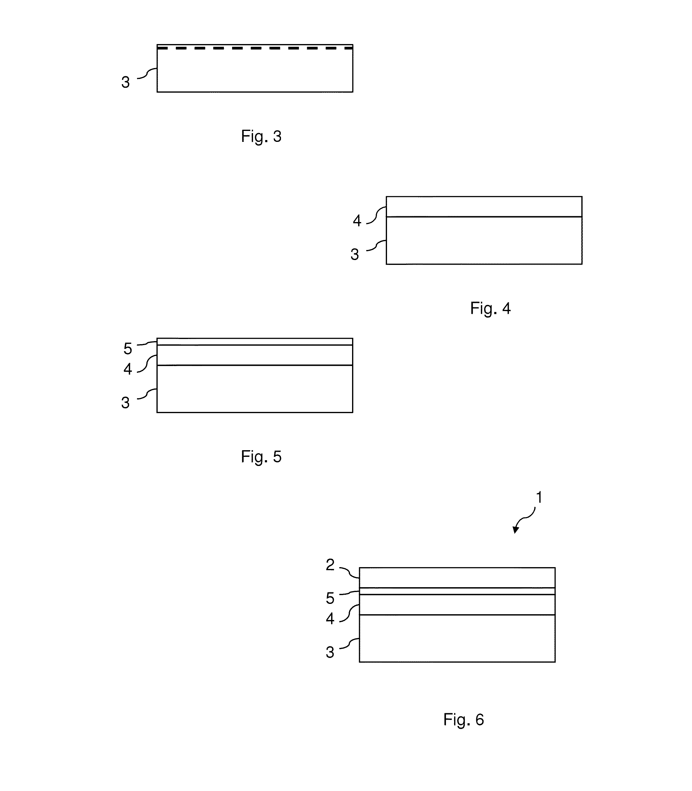
A semiconductor structure (1) comprises a dielectric layer (2) including a dielectric material having a dielectric constant higher than that of silicon oxide; a channel region (3) including a compound semiconductor material; a passivation layer (4) including a passivation material between the channel region (3) and the dielectric layer (2); and a barrier layer (5) including a barrier material between the dielectric layer (2) and the passivation layer (4) for reducing a chemical reaction of the dielectric material of the dielectric layer (2) with the passivation material of the passivation layer (4).

Description

FIELD OF INVENTION[0001]This disclosure relates to a semiconductor structure, and more particularly to a semiconductor structure including a dielectric material having a dielectric constant of greater than that of silicon dioxide, as for example a hafnium-based dielectric, and a compound semiconductor. This disclosure also provides a method of fabricating such a semiconductor structure.BACKGROUND[0002]In conventional semiconductor technology silicon (Si) is the principal semiconductor material and silicon dioxide (SiO2) is used as gate oxide material in CMOS transistors. However, the continuous downscaling of semiconductor devices requires better dielectrics than SiO2 to achieve a thinner gate dielectric with acceptable leakage currents. Such dielectrics are called high-k dielectric materials. Additionally, alternative semiconductor materials having a higher charge carrier mobility than Si are required to follow the international technology roadmap for semiconductors (ITRS).[0003]Ca...

Claims


Application Information

Patent Timeline
Patent Type & Authority Applications(United States)
IPC IPC(8): H01L29/78H01L21/20
CPCH01L29/78H01L21/28264H01L29/495H01L29/513H01L29/517H01L29/66181H01L29/66477H01L29/94H01L29/20
Inventor CZORNOMAZ, LUKASEL KAZZI, MARIOFOMPEYRINE, JEANMARCHIORI, CHIARA
Owner IBM CORP
Learn More