

Dye, photoelectric conversion element using the same, photoelectrochemical cell, and method of producing dye
a technology of photoelectric conversion element and dye, which is applied in the direction of sustainable manufacturing/processing, non-metal conductor, final product manufacturing, etc., can solve the problems of high cost of ruthenium complex dye, inability to meet the requirements of ruthenium supply, etc., to achieve high photoelectric conversion efficiency, low cost, and favorable characteristics
- Summary
- Abstract
- Description
- Claims
- Application Information
AI Technical Summary
Benefits of technology
Problems solved by technology
Method used
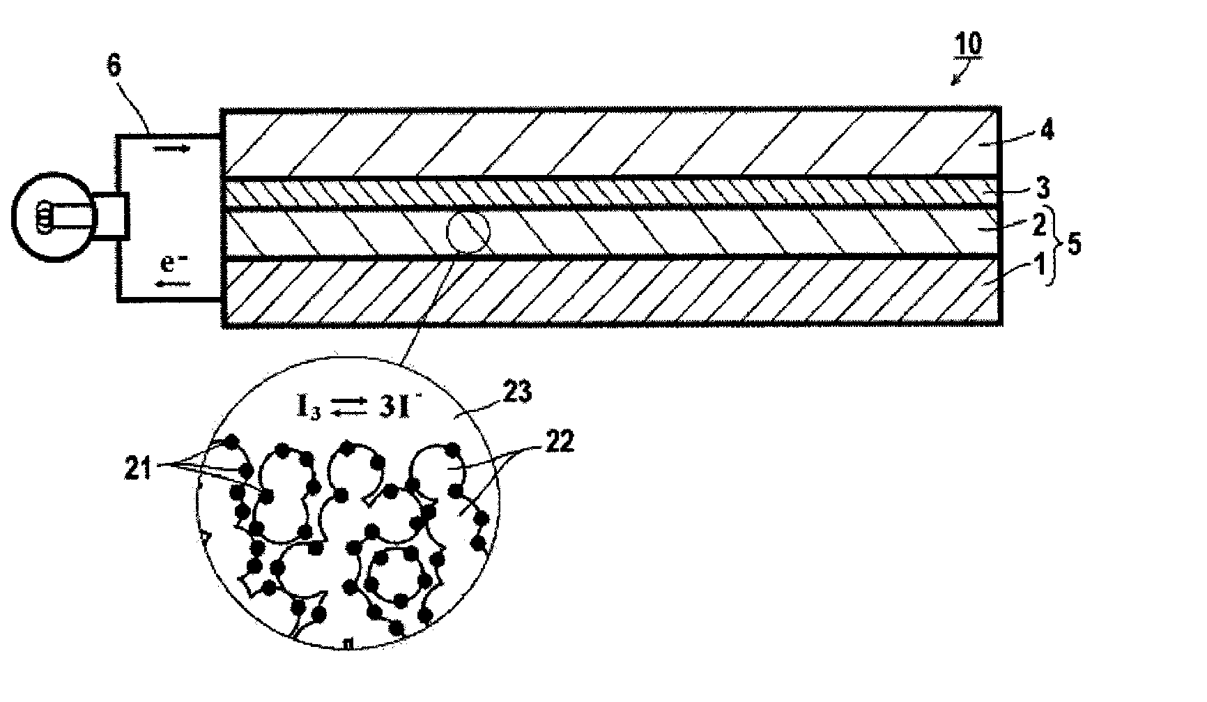
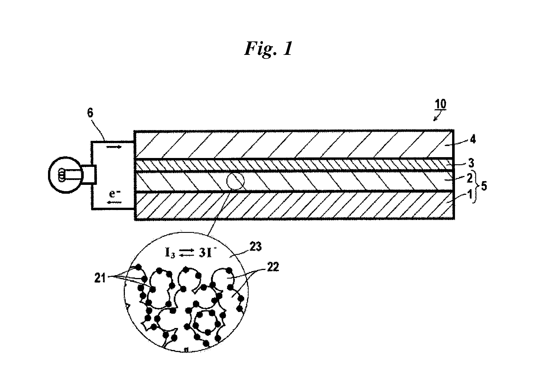
Image

Examples
first embodiment
1. Dye for Use in the Present Invention
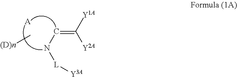
[0045]Development of a dye used in dye-sensitized photoelectric conversion elements has been traditionally focused mainly on the donor site. There, attention was paid to a dye having a cyclic compound introduced to the adsorption site, and thorough investigations were made. As a result, it was found that there can be provided a photoelectrochemical cell having high conversion efficiency which is capable of absorbing up to a relatively long wavelength region in the solar spectrum, by the first embodiment of the present invention using a particular dye (dye compound), as a sensitizing dye, in which a cyclic structure formed from carbon atoms and nitrogen atoms has an acidic group linked to the nitrogen atom of the cyclic structure via a single bond or divalent linking group, and an exomethylene of the cyclic structure is substituted with one or more acidic groups. The present invention was made based on this finding.
[0046]The dye having a structu...
second embodiment
2. Dye for Use in the Present Invention
[0111]As a result of intensive investigation, the present inventors have found that introduction of the following three design concepts makes it possible to obtain dyes (dye compounds) of the second embodiment of the present invention and the third embodiment of the present invention, each of which imparts high photoelectric conversion efficiency and also has excellent durability. Further, they have found that each of a photoelectric conversion element containing semiconductor particles sensitized with the dye and a photoelectrochemical cell equipped with the photoelectric conversion element as a component has a high photoelectric conversion efficiency.
[0112]In order to promote delocalization of cation radicals, one-electron oxidation state of the dye is stabilized by introducing a donor site having a widespread conjugation system.
[0113]It is presumed that high photoelectric conversion efficiency can be obtained by broadening an absorption regi...
synthesis example 1-1
Preparation of Exemplified Dye D-1
[0300]The exemplified dye D-1 was prepared according to the method shown in the following scheme 1.
(i) Preparation of Compound D-1-a
[0301]To 600 mL of DMF containing 62.0 g of allyl cyanoacetate and 71.9 g of ethyl isothiocyanatoacetate, 77.7 g of DBU was added dropwise at 0° C., and then the mixture was stirred for 1 hour. 82.7 g of ethyl bromoacetate was added to the mixture, and the resultant was stirred at 40° C. for 1 hour. Then, the temperature of the reaction mixture was reduced to room temperature and then water was added. The precipitated crystals were collected by filtration. By crystallization from methanol, 142.1 g of Compound D-1-a was obtained.
(ii) Preparation of Compound D-1-b
[0302]Was stirred 10 g of Compound D-1-a in acetic acid / hydrochloric acid=2 / 1 for 2 hours. After the temperature of the reaction mixture was adjusted to room temperature, water and ethyl acetate were added thereto. The extracted organic layer was washed with wate...
PUM
 Abstract
Description
Claims
Application Information