Resin substrate having metal film pattern formed thereon

a metal film pattern and resin substrate technology, applied in the direction of resistive material coating, metallic material coating process, printing, etc., can solve the problems of low heat resistance of the adhesive bonding between the resin film substrate and the copper foil, difficult to etch the metal film pattern with high accuracy, and low adhesiveness of the metal film. , to achieve the effect of reducing the concentration of metal ions, reducing the occurrence of metal ions, and excellent reliable adhesion

Active Publication Date: 2014-06-26
SEIREN CO LTD
View PDF14 Cites 3 Cited by
  • Summary
  • Abstract
  • Description
  • Claims
  • Application Information

AI Technical Summary

Benefits of technology

[0037]According to the method of the present invention, a resin substrate having a metal film pattern excellent in reliable adhesion can be produced. According to the method of the present invention, adhesives are not used on the interfacial surface between the metal film and the resin. An etching process for forming a pattern is not used either. Therefore, the present invention enables to solve the problems of deterioration of reliable adhesion of a metal film caused by adhesives and / or corrosion by an etching solution which had been problems of conventional art.
[0038]According to the present invention, in addition, the use of an acidic treatment liquid containing a reducing agent in the process of reducing a metal salt would bring about less occurrence of falling of metal ions in the post process. Therefore, the processes can be carried out with a lower metal ion concentration as compared with a conventional technology, which is excellent in terms of practical utility.
[0039]Furthermore, by regulating viscosity of a latent image agent and / or by employing a gravure printing technology, it would be possible to form a fine pattern having excellent accuracy.

Problems solved by technology
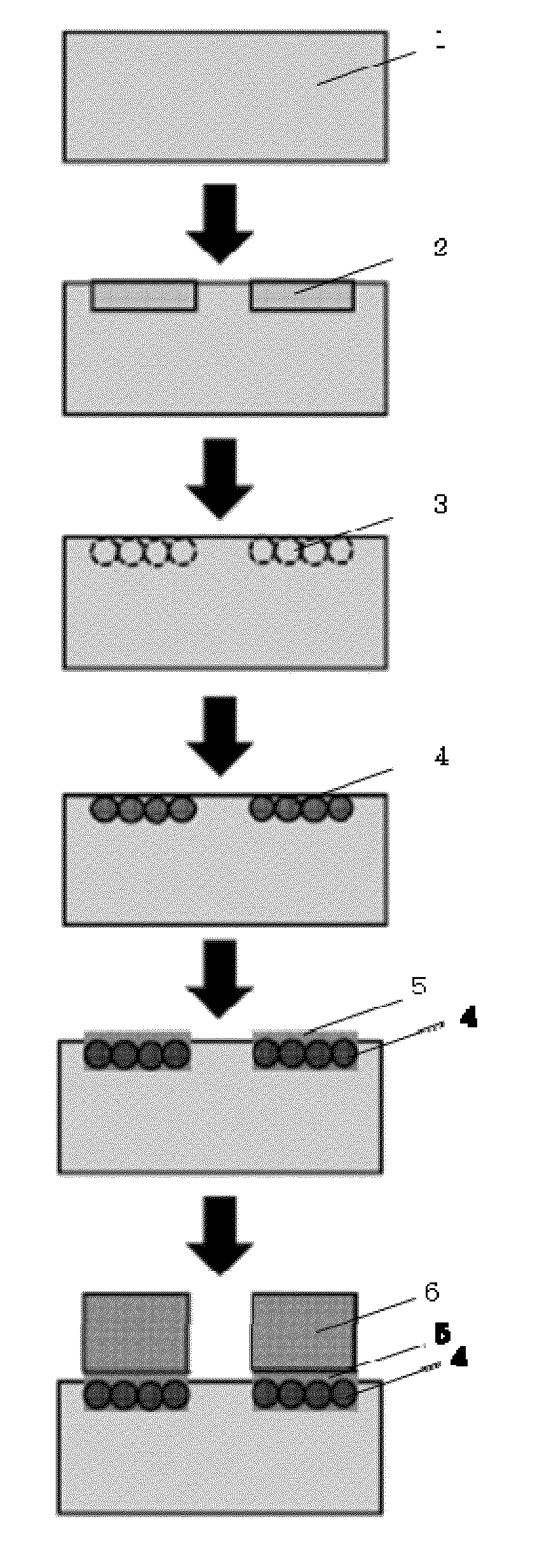
On the other hand, the above-mentioned conventional method has problems such that heat resistance of the adhesive bonding a resin film substrate and copper foil is low, and as a result, adhesiveness of the metal film becomes low.
According to the above-mentioned etching process, in addition, it may be difficult to etch a metal film pattern with high accuracy since it is difficult to control the rate of dissolving of the metal film.
Furthermore, it is known that the bonded interfacial surface of the metal film and resin is corroded by an etching liquid, and it might cause deterioration of adhesiveness particularly in the case of a fine pattern.
Accordingly, in a manufacturing process comprising an etching process, there has been a problem such that it is difficult to handle a fine pattern with high adhesiveness such as a fine pattern having a width of several dozen micrometers (μm).
However, in the case of using an evaporation method, reliable adhesion is insufficient in some cases.
In the case of using a sputtering method, adhesion strength is expected to be high but an etching process is required for forming a metal film pattern and there remains a problem such that it is difficult to deal with making a pattern finer.
However, there is a problem in adhesion strength between paste or ink and a resin.
In addition, paste and ink to be used are highly expensive.
Furthermore, the conductive pattern obtained by these methods has high electric resistance, and therefore, electrical property as a metal film is insufficient.
In the etching process, the metal film on the interfacial surface of the resin might be corroded and there still remains a problem that it is difficult to deal with a thin line pattern having highly reliable adhesion.
However, since a low-viscosity solution is discharged according to the ink-jet process in general, there are problems such as bleeding and / or repelling of the alkali solution on the polyimide resin, which might cause difficulty in forming a fine pattern.
In addition, the above-mentioned patent document does not disclose a finding concerning suppression of the falling of metal ions in the metal ion reduction process.
Therefore, there is a problem that it is necessary to use a highly-concentrated metal ion solution.
Furthermore, it might be unable to adsorb sufficient metal ions for forming an inorganic thin film.

Method used


Image

  • Resin substrate having metal film pattern formed thereon
  • Resin substrate having metal film pattern formed thereon
  • Resin substrate having metal film pattern formed thereon

Examples


example 1

[0094]A polyimide resin substrate for printing of a latent image agent was prepared by cutting a polyimide film having a width of 30cm and a thickness of 25 μm, brand name “Kapton H” manufactured by DU PONT-TORAY CO., LTD., to a proper size. Subsequently, pattern-printing of a latent image agent onto the surface of said polyimide resin substrate was carried out by using a gravure printer.

[0095]The latent image agent used here was prepared by adding carboxymethyl cellulose and a thixotropic agent for regulating viscosity appropriately to a solution comprising potassium hydroxide (KOH) as an alkaline compound with the alkali concentration of 3M. The viscosity of the latent image agent, measured by a cone-plate viscometer at 25° C. with a rotor rotation number of 0.5 rpm, was 370 Pa·s.

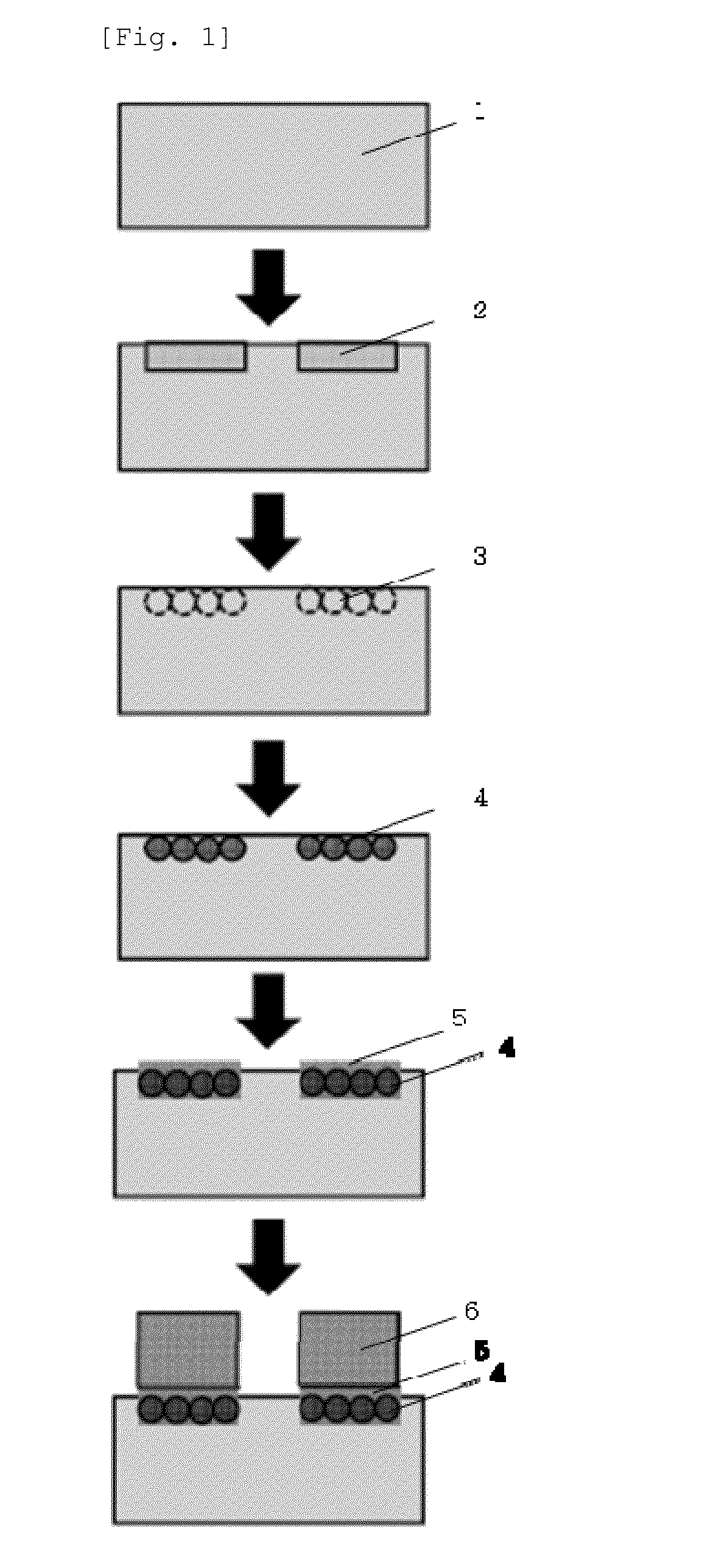
[0096]As for pattern-printing, gravure printing was carried out by using a gravure printing plate having a linear engraved groove shown in FIG. 2. The engraved groove of the gravure printing plate has a l...

example 2

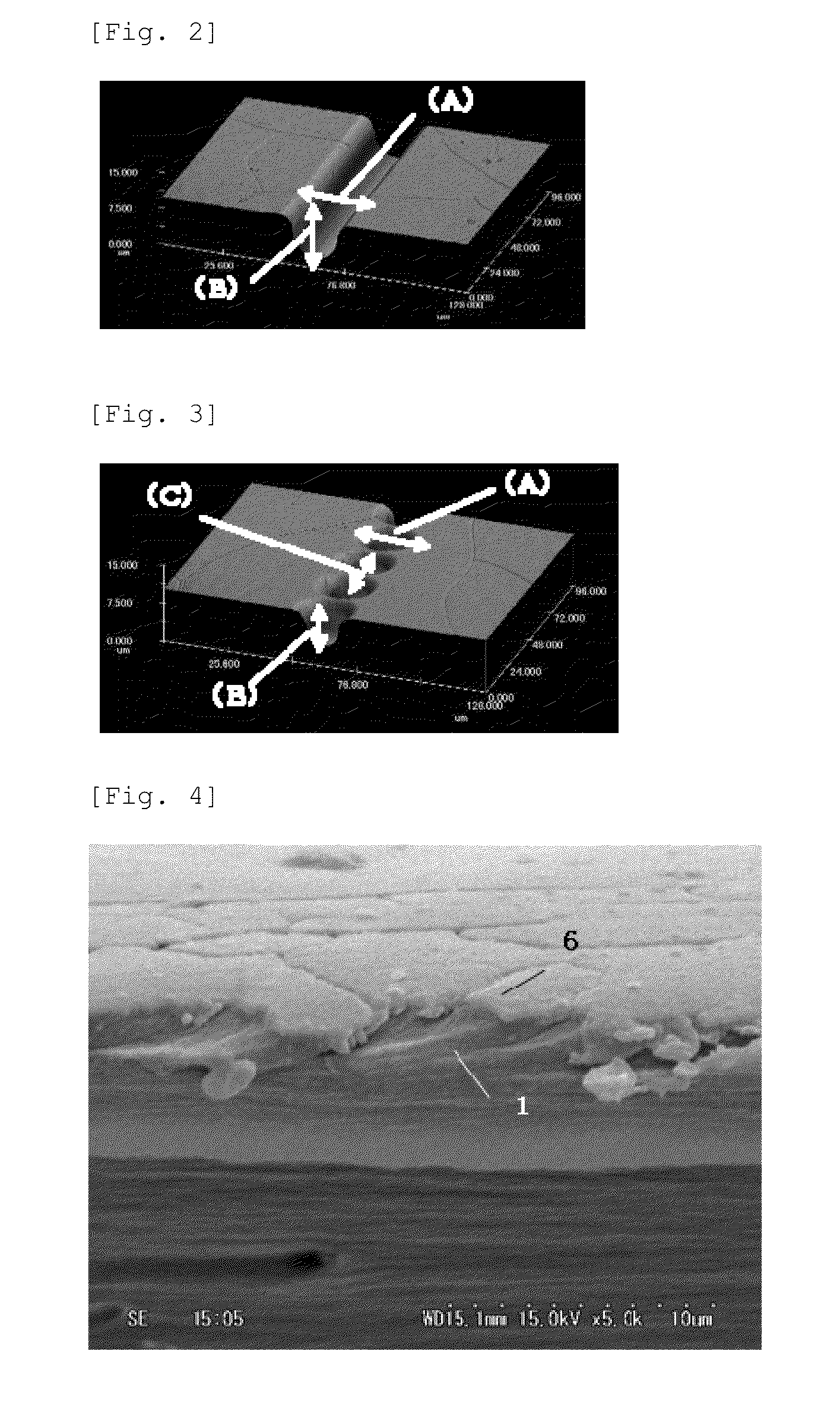
[0103]In this example, gravure printing was carried out by using a gravure printing plate having a dot-shaped engraved groove shown in FIG. 3 was used for gravure printing. The width of a side of a dot of the engraved groove of said gravure printing plate was 20 μm, the depth was 6 μm and the distance between the centers of recessed parts of the dots was 22 μm. An experiment was carried out by adjusting other conditions same as in Example 1, whereby a printed pattern having a line width of 27 μm was formed on the polyimide resin substrate.

[0104]By carrying out the same steps as in Example 1, a polyimide resin substrate on which a metal film pattern having a line width of 30 to 40 μm and a metal film thickness of 4 μm was formed was obtained.

example 3

[0105]In this example, aqueous solutions of palladium chloride having concentrations of 0.85 mM, 0.43 mM, 0.085 mM and 0.0085 mM respectively was used. Experiments were carried out by adjusting other conditions same as in Example 1 until the step of electroless nickel plating. A comparative experiment was also carried out at the same time by using an aqueous solution having a 0 mM palladium chloride concentration.

[0106]Evaluation of selective deposition of nickel plating was performed under the following standard:[0107]X; Not Deposited[0108]◯: Deposited

[0109]The result of evaluation was shown in Table 2. By the above process, selective deposition of plating was found in the modified area imprinted with a latent image agent in all the cases of using an aqueous solution of palladium chloride.

(Adhesion Test)

[0110]The samples wherein deposition of nickel plating were found in Example 3 (evaluation; ◯) were brought into an electroless copper plating process under the same conditions as i...


PUM

PropertyMeasurementUnit
viscosityaaaaaaaaaa
widthaaaaaaaaaa
depthaaaaaaaaaa

Abstract

The purpose of the present invention is to provide a method for using a metal ion solution of low concentration to efficiently form a metal film pattern of excellent accuracy and reliable adhesion on a resin substrate. A resin substrate having a metal film pattern formed thereon is produced by a method that includes the following steps (a) to (e): (a) a step for pattern-printing of a latent image agent (2) onto the surface of a resin substrate (1) ; (b) a step for bringing the area imprinted with the latent image agent (2) into contact with a solution containing metal ions, and forming a metal salt (3); (c) a step for bringing the metal salt (3) into contact with an acidic treatment liquid containing a reducing agent, and reducing the metal salt; (d) a step for forming an electroless nickel plating film (5) on the area imprinted with the latent image agent; and (e) a step for precipitating an electroless copper plating (6) onto the surface of the nickel plating film (5).

Description

TECHNICAL FIELD[0001]The present invention relates to a method for producing a resin substrate having a metal film pattern formed thereonBACKGROUND ART[0002]A resin material having a metal film pattern formed thereon has long been used in the field of electronics parts, decorative products and the like. For example, a film having a metal film formed as a circuit pattern on the surface of a resin substrate has widely been used as a flexible printed circuit board or the like. Conventionally, formation of a metal film pattern on the surface of a resin substrate has been carried out commonly by a process of firstly laminating the resin film substrate with a copper foil through an adhesive to produce a copper-clad laminate, drawing a desired pattern thereon, and dissolving copper foil of the part other than the pattern to remove by an etching process.[0003]In association with the recent development of the electronics industry, however, demands for making a metal film pattern finer and fo...

Claims


Application Information

Patent Timeline
Patent Type & Authority Applications(United States)
IPC IPC(8): H05K3/18
CPCH05K3/185H05K3/182B41M1/30H05K2201/0154C23C18/1608C23C18/1651C23C18/2086C23C18/30C23C18/36C23C18/405H05K2203/0793B41M1/10H05K3/18B05D1/28B05D5/12B05D7/52
Inventor BAMBA, AKIMITSUTSUJIMOTO, KAZUHISAYAMADA, HIDEYUKIKUGIMIYA, KOUICHI
Owner SEIREN CO LTD
Why Eureka
Try Eureka