Method of forming flexible and tunable semiconductor photonic circuits

a semiconductor photonic circuit and flexible technology, applied in the field of forming flexible and tunable semiconductor photonic circuits, can solve the problems of inability to adapt or re-programme silicon photonic devices, lack of high electrical performance of crystalline inorganic semiconductor materials, and fixed silicon photonic devices that cannot be adapted or re-programmed, etc., to achieve the effect of preserving optical functionalities and performance, tuning over a large range, and reducing contact area and overall bonding for

Inactive Publication Date: 2014-08-21
RGT UNIV OF MINNESOTA
View PDF6 Cites 22 Cited by
  • Summary
  • Abstract
  • Description
  • Claims
  • Application Information

AI Technical Summary

Benefits of technology

[0008]The present invention is particularly directed to methods to physically transfer highly integrated devices made in high-quality, crystalline semiconductors, such as silicon, on to flexible substrates, such a comprising plastic or polymeric materials. The present invention includes methods of making a flexible form of semiconductor photonic devices using a transfer-and-bond fabrication method. With such methods, photonic circuits including, as examples, interferometers and resonators can be formed and then transferred onto flexible substrates with preserved optical functionalities and performance. Moreover, by controllably mechanically deforming an optical circuit or device of the present invention, one or more optical characteristics of the circuit or device can be tuned over a large range. Advantageously, such tuning can be controlled to be reversible. Flexible photonic systems of the present invention that are based on a semiconductor-on-plastic (SOP) platform, opens the door to many future applications, including tunable photonics, opto-mechanical sensors, and biomechanical and biophotonic probes.
[0009]Generally, methods of the present invention include, after forming a semiconductor photonic circuit (such as of crystalline silicon) on a rigid silicon substrate, removing substrate material (e.g., from a buried oxide layer such as SiO2 provided as a top layer to the silicon substrate) from below the semiconductor photonic circuit to reduce the contact area and overall bonding force between the semiconductor circuit and the substrate (the buried oxide layer). With the bonding force decreased, the semiconductor circuit can be removed from the substrate by the application of a sufficient force. Preferably, a flexible material layer is sufficiently bonded to top surface(s) of the semiconductor circuit prior to removal so that the semiconductor circuit is transferred to the flexible layer during the removal step. As such, transfer of the semiconductor circuit from its original substrate to a flexible substrate, such as a plastic substrate, can be done with a precision preferably so that no greater than 10 nanometers of displacement or distortion occurs to any portion of the circuit.

Problems solved by technology

These silicon photonic devices are fixed on-chip and cannot be adapted or re-programmed because of this.
These flexible microelectronic devices exhibit mechanical flexibility and the bio-compatibility, however, they lack the high electrical performance of crystalline inorganic semiconductor materials.

Method used


Image

  • Method of forming flexible and tunable semiconductor photonic circuits
  • Method of forming flexible and tunable semiconductor photonic circuits
  • Method of forming flexible and tunable semiconductor photonic circuits

Examples


example

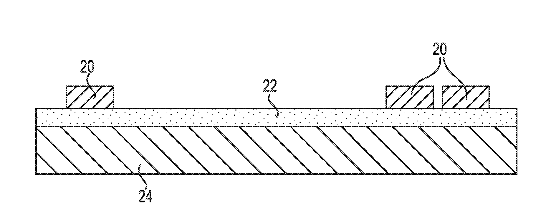
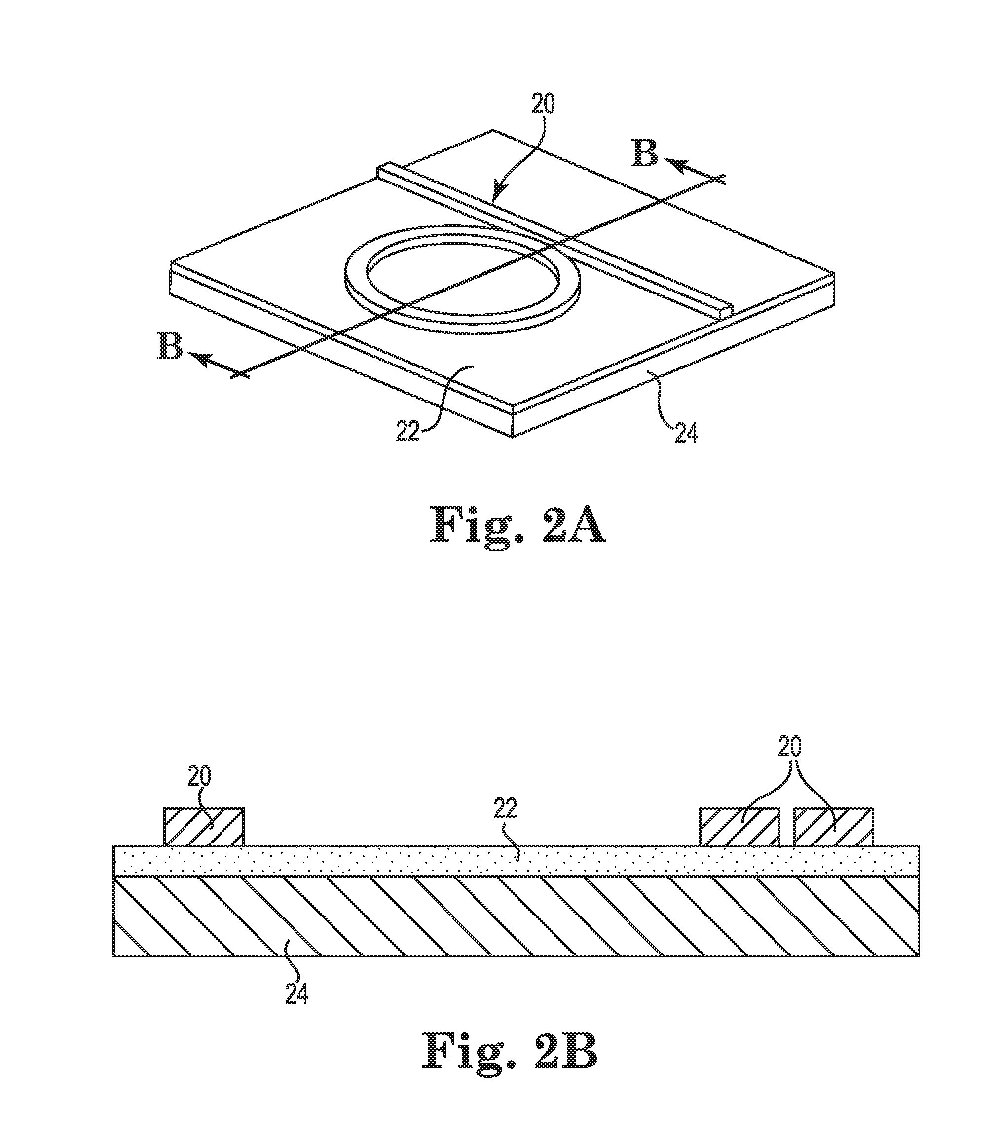
[0068]The following exemplary method of the present invention is schematically illustrated in FIGS. 24 through 28. On a standard silicon-on-insulator wafer (SOITEC, Unibound, 220 nm top silicon layer, 3 μm buried oxide layer) (FIG. 24), a silicon photonic circuit was patterned using one-step electron beam lithography (Vistec, EBPG 5000+) and plasma dry etching (Trion II ICP-RIE) with chlorine based chemistry. The resulting circuit is shown in FIG. 25. Subsequently, the substrate was etched in 10:1 buffered oxide etch (BOE) solution, for a precise period of time and at a precisely controlled temperate, to etch the buried oxide (BOX) layer and undercut the silicon device layer, as shown in FIG. 26. The undercut reduced the interfacial area between the silicon and the BOX layer so that the total bonding force between them was reduced without separating them. After etching, the silicon device layer was still affixed to the substrate so that the silicon circuits did not move. In the next...


PUM


Abstract

Methods to physically transfer highly integrated silicon photonic devices from high-quality, crystalline semiconductors on to flexible plastic substrates by a transfer-and-bond fabrication method. With this method, photonic circuits including interferometers and resonators can be transferred onto flexible plastic substrates with preserved optical functionalities and performance.

Description

CROSS-REFERENCE TO RELATED APPLICATION[0001]This application claims the benefit of U.S. Provisional Application No. 61 / 765,921 filed Feb. 18, 2013, titled METHOD OF FORMING FLEXIBLE AND TUNABLE SEMICONDUCTOR PHOTONIC CIRCUITS, the entire contents of which are incorporated herein by reference for all purposes.GOVERNMENT RIGHTS[0002]This invention was made with government support under ECCS1232064 awarded by the National Science Foundation. The government has certain rights in the invention.BACKGROUND OF THE INVENTION[0003]Silicon photonics is a technology that can be used to provide high-performance, chip-scale and chip-to-chip communication networks with low cost. Unlike on-chip electrical interconnects in which multiple metal layers are used to transport electrical signals, silicon-photonic interconnects typically use integrated silicon waveguides to route optical signals. Such silicon waveguides typically comprise a path or pattern of crystalline silicon that is formed onto a rigi...

Claims


Application Information

Patent Timeline
Patent Type & Authority Applications(United States)
IPC IPC(8): H01L21/306
CPCH01L21/306G02F1/025G02B6/12007G02B6/136G02B2006/12061G02B2006/12138H01L21/7806
Inventor LI, MOCHEN, YU
Owner RGT UNIV OF MINNESOTA
Why Eureka
Try Eureka