Cobalt chrome coated titanium implant

Active Publication Date: 2014-09-04
HOWMEDICA OSTEONICS CORP
View PDF3 Cites 0 Cited by
  • Summary
  • Abstract
  • Description
  • Claims
  • Application Information

AI Technical Summary

Benefits of technology

[0020]Because of the high hardness, the CoCr coating was scratched less depth (6.5 μm) than forged CoCr (9.3 μm) under a clinically relevant 30 N load using a diamond stylus. This means that the CoCr coating of the present invention is more wear resistant than a standard bulk CoCr bearing surface against a third body. In addition, with a coating thickness of 13 μm, the scratch only penetrated half of the coating thickness, and thus the CoCr coating of the present invention has better third body wear resistance than predicted for a CoCr forged cup.
[0021]The advantage of the multi-arc PVD process is a high deposition efficiency and suitability for coating concave cup inner sphere geometries, as compared to other PVD processes. The coating process mapping has demonstrated the coating uniformity in the different locations in a production equipment chamber. The coating thickness of 16-19 μm in the inner sphere of a forced CoCr cup was achieved. The coating was able to be polished to 13 μm with a mirror finish (Ra<20 nm).
[0022]The PVD CoCr coating of the present invention has a strong interface bonding. The adhesive tensile bond strength was over 110 Mpa on blasted surfaces. The bond strength did not change in simulated body fluid at 22 week

Problems solved by technology

John Chanley's low wear and low friction concepts, but the small size bearing had a high dislocation rate.
They found that after testing the CoCr coating had scratching, cracking, peeling and having tribocorrosion.
Post revision inspection indicated that some area of CoCr coating was completely destroyed.
The delaminated CoCr particles contributed to third body wear.
However, the CoCr coating appeared to be either not polished, or poorly polished, Ra=0.1 micron (100 nm) according to atomic force microscopy.
Overall, the MS-PVD CoCr coatings performed worse than conventional bulk CoCr as bearing surfaces.
Another factor is the low bond strength of the coating to the substrate.
Also, CoCr coating on CoCr substrate does not in

Method used


Image

  • Cobalt chrome coated titanium implant
  • Cobalt chrome coated titanium implant
  • Cobalt chrome coated titanium implant

Examples


Embodiment Construction

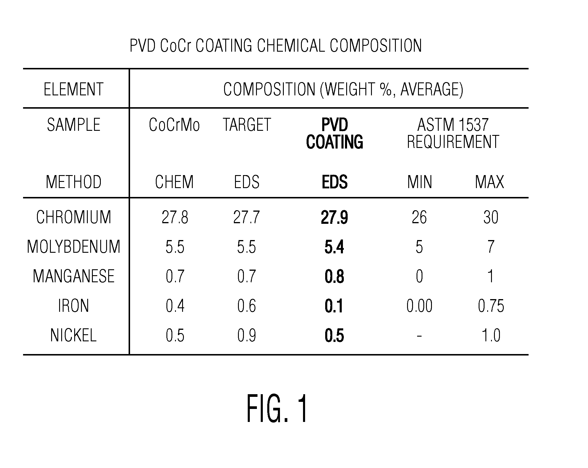
[0037]Referring to FIG. 1, there is shown the chemical composition of the PVD cobalt-chrome molybdenum coating of the present invention compared to a forged cobalt-chrome molybdenum implant material meeting the requirements of ASTM 1537. It can be seen that in all of the top five components of the alloy the coating of the present invention is within the ASTM specification requirements. The analysis of the CoCrMo coating was performed both chemically and by energy-deispersive x-ray spectroscopy.

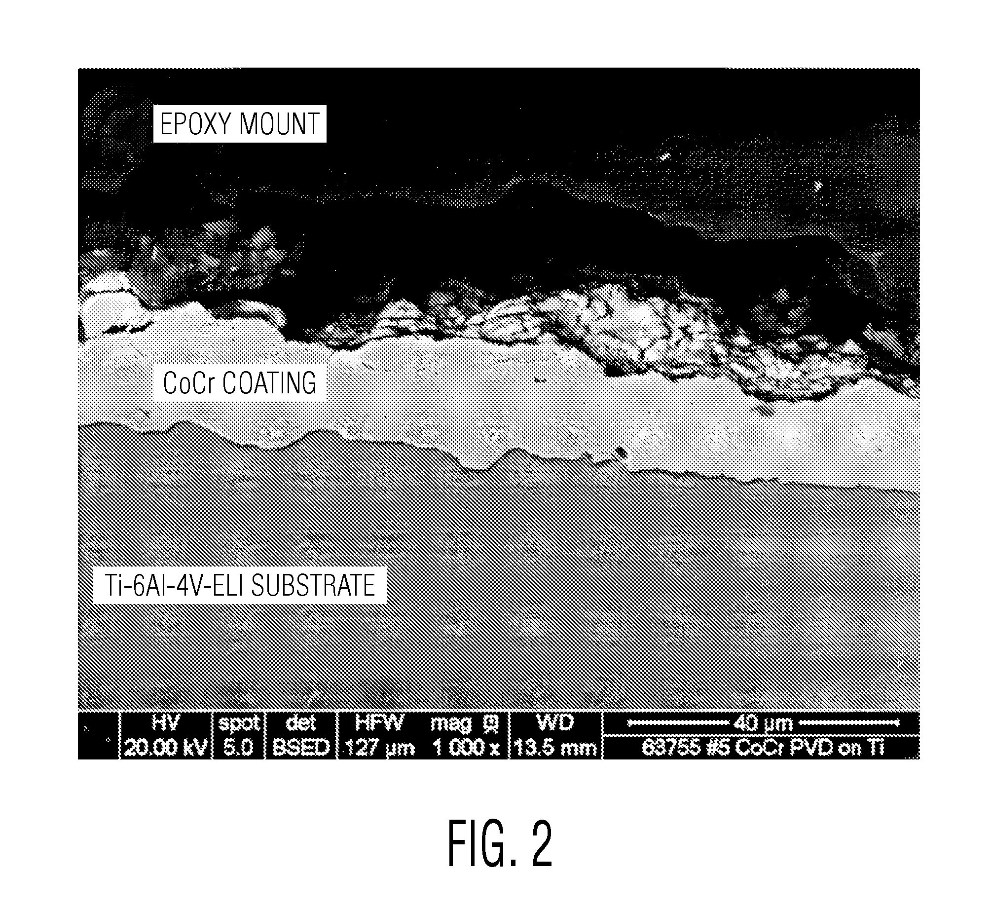
[0038]Referring to FIG. 2 there is a scanning electron microscope photograph of a cross-section of the coating which was approximately 23.5 microns thick. The substrate was commercially available titanium alloy Ti6Al4VELI.

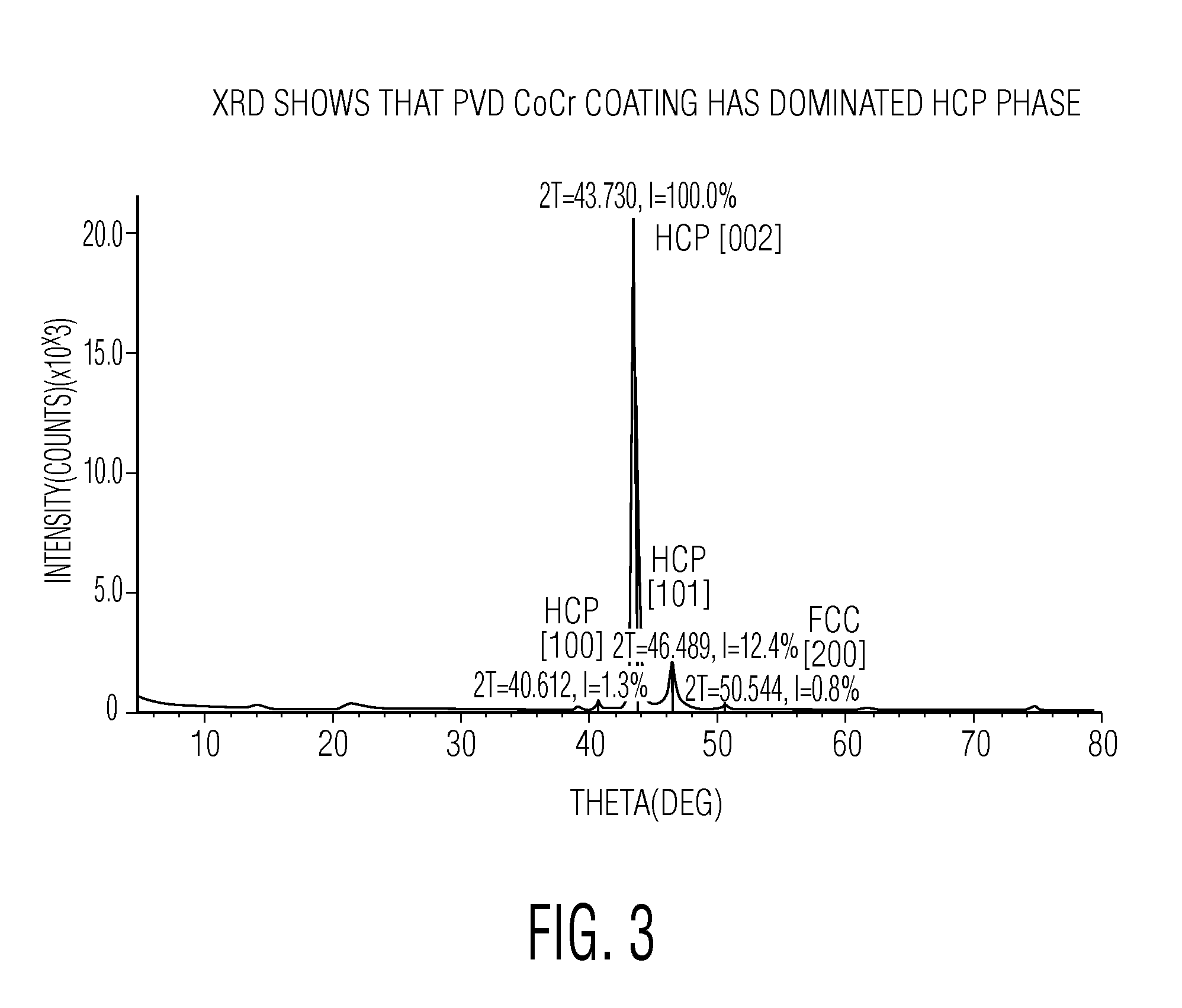
[0039]Referring to FIG. 3 there is an x-ray defraction pattern showing that the PVD coating of the present invention has a very high percentage of hexagonally-close-packed phase. This is exactly the opposite of standard forged cobalt-chrome molybdenum implant alloys which hav...


PUM

PropertyMeasurementUnit
Grain sizeaaaaaaaaaa
Lengthaaaaaaaaaa

Abstract

An orthopedic implant has a prosthetic joint component made, for example, of polyethylene and another component made of a titanium or titanium alloy substrate. The substrate has a first bearing surface coated with a coating made of a cobalt-chromium molybdenum alloy. The bearing surface slidably receives a second bearing surface of the prosthetic joint component. The cobalt-chromium molybdenum alloy coating forming the first bearing surface is made up of hexagonal close packed (HCP) grains having a columnar structure with a length of about 1 μm and a width of about 0.1 μm with the length of each HCP grains being oriented generally perpendicular to the titanium substrate bearing surface.

Description

BACKGROUND OF THE INVENTION[0001]This invention relates to a bearing surface for an orthopedic implant which is made of a Cobalt Chrome molybdenum alloy coating deposited on a titanium (Ti) substrate.[0002]In the 1960's to the 1990's, smaller head size metal-on-UHMWPE bearings (22-28 mm) were widely used in orthopedic industry based on Dr. John Chanley's low wear and low friction concepts, but the small size bearing had a high dislocation rate. Between 2000-2010, larger size metal-on-metal bearing (32-44 mm) were used. These significantly decreased the dislocation rate. In recent years, Stryker Corp. introduced dual mobility or bi-polar acetabular cup systems, which combined all benefits of both small bearings' low friction and large bearings' low dislocation rate.[0003]It is desirable to make a new dual mobility cup that has the combined functional features of the current dual mobility acetabular cups, especially having a 3D titanium foam structure for bone ingrowth, while the bear...

Claims


Application Information

Patent Timeline
IPC IPC(8): A61L27/30A61F2/34
CPCA61F2/34A61L27/306A61F2/30767A61F2/3094A61F2/32A61F2002/30934A61F2002/3208A61F2310/00023A61F2310/00413A61L27/06A61L2420/02A61L2420/08A61L2430/02C23C14/16
Inventor ZHANG, ZONGTAOHANSON, KEENAN MICHAELMCCARTHY, THOMAS FRANCISLAWRYNOWICZ, DANIEL E.WANG, AIGUO
Owner HOWMEDICA OSTEONICS CORP
Why Eureka
Try Eureka