Eureka AIR delivers breakthrough ideas for toughest innovation challenges, trusted by R&D personnel around the world.

Durable Hydrophilic Dry Adhesives with Hierarchical Structure and Method of Making

a hydrophilic dry adhesive and hierarchical structure technology, applied in the direction of film/foil adhesives, plasma techniques, transportation and packaging, etc., can solve the problems of surface modification of fibril tips involving uvo or plasma treatment, and the approach taken to alternation of surface properties, etc., to improve wettability, reduce water contact angle, and change the surface morphology

Inactive Publication Date: 2014-11-06
BOARD OF TRUSTEES OPERATING MICHIGAN STATE UNIV +1
View PDF2 Cites 17 Cited by
  • Summary
  • Abstract
  • Description
  • Claims
  • Application Information

AI Technical Summary

Benefits of technology

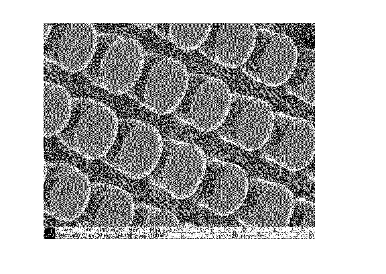
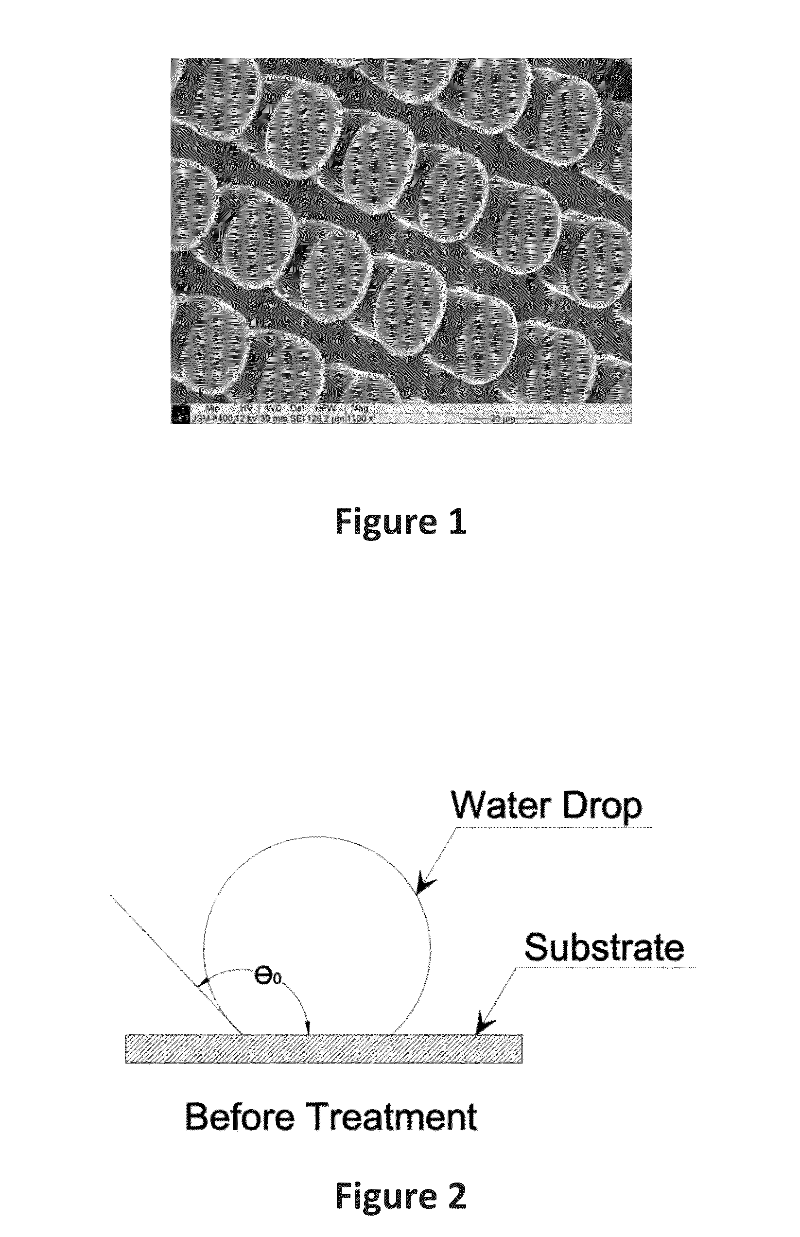
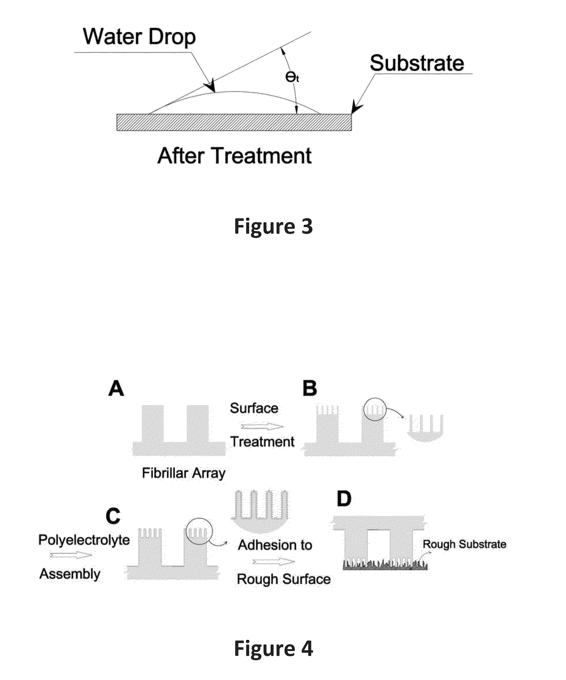
The invention describes methods for improving the wettability and surface morphology of polymer microfibrillar structures, which can be used as bio-inspired adhesives. Two techniques are used for this purpose: UVO treatment and plasma treatment. UVO treatment involves using short-wavelength UV radiation to excite molecules on the surface, while plasma treatment involves using high-energy ions to oxidize the surface and create nanostructured tips. These modifications make the polymer microfibrils more hydrophilic, which enhances their adhesion in humid environments. Additionally, coating the surface with a polyelectrolyte can improve the stability of the adhesive. The invention provides a practical, low-cost, high-throughput, and scalable process for producing stable and highly adhesive microfibrillar structures.

Problems solved by technology

All the above cited prior arts have been focused on the geometrical design (i.e. dimensions and spacing of the pillars, shapes of the tips, mechanical properties of the materials); none of them discloses the approach taken here to alternation of the surface properties of dry adhesives to enhance adhesion.
Furthermore, plasma treatment causes breakage of chemical bonds because it involves bombardment of the polymer surface with ions of high energy, thus creating dangling bonds which react with the hydroxyl groups from atmosphere when exposed to air.
Surface modification of fibril tips involving UVO or plasma treatment tends to degrade (experiencing hydrophobic recovery) over time.

Method used


Image

  • Durable Hydrophilic Dry Adhesives with Hierarchical Structure and Method of Making
  • Durable Hydrophilic Dry Adhesives with Hierarchical Structure and Method of Making
  • Durable Hydrophilic Dry Adhesives with Hierarchical Structure and Method of Making

Examples


example

[0047]Step 1: Fabrication Process of Polymer Microfibrillar Structure

[0048]Polymer microfibrillar structures were produced by soft-molding of elastomeric precursors on micro fabricated template. This approach can be used for fabrication of fibrils of any dimensions. The template was produced by the photolithographic process, which is a prevailing method of batch-transferring micro-scale patterns. In the photolithography process, an ultraviolet light shines through a two-dimensional photomask onto a light-sensitive chemical photoresist applied upon a substrate. This process removes the photoresist at undesired areas, leaving a three-dimensional (fibrillar) structure on the substrate, with a height that is equal to the thickness of the photoresist. This remaining photoresist structure is then used in a micro-molding process. For the purpose of fabricating the lithographic SU-8 templates, a glass wafer was used to prevent UV reflections during lithography. A thin layer of diluted SU-8 ...


PUM

PropertyMeasurementUnit
diameteraaaaaaaaaa
diameteraaaaaaaaaa
water contact angleaaaaaaaaaa

Abstract

Provided is a method of making durable hydrophilic and hierarchical structures containing nano and micro features used as dry adhesives. The method includes introduction of hydrophilic, nanostructured features on the micro-scale tips of fibrillar arrays through UV / Ozone (UVO) and oxygen plasma treatment; the method also includes further coating of the hierarchical structure with a polyelectrolyte via electrostatically-driven self-assembly to improve the hydrophilic stability of the treated fibril tip surfaces.

Description

FEDERALLY SPONSORED RESEARCH OR DEVELOPMENT[0001]The present invention was supported in part by Grant Number FA8651-07-C-0092 awarded by the U.S. Air Force. The U.S. Government may have certain rights in the invention.CROSS-REFERENCE TO RELATED APPLICATIONS[0002]Not applicable.BACKGROUND—PRIOR ART[0003]The following is a tabulation of some prior art that presently appears relevant:U.S. Patents[0004]Patent NumberKind CodeIssue DatePatentee7,632,417B22009 Dec. 15Suh et al.7,479,198B22009 Jan. 20Guffrey et al.7,479,318B22009 Jan. 20Jagota et al.U.S. Patent Application Publications[0005]Publication No.Kind CodePubl. DateApplicant2010 / 0136281A12010 Jun. 03Sitti et al.2009 / 0114618A12009 May 07Zhang et al.2009 / 0041986A12009 Feb. 12Zhang et al.Nonpatent Literature Documents[0006]C. de Menezes Atayde and I. Doi (2010). “Highly stable hydrophilic surfaces of PDMS thin layer obtained by UV radiation and oxygen plasma treatments.”Phys. Status Solid C 7: 189-192.[0007]A. del Campo, C. Greiner an...

Claims


Application Information

Patent Timeline
Patent Type & Authority Applications(United States)
IPC IPC(8): C09J179/02C09J7/00B05D3/06
CPCC09J179/02B05D3/068C09J7/00B05D2256/00B05D2201/02C09J2201/626B05D2518/10B05D2502/005B05D2518/00B05D2350/00B05D2503/00B05D5/08C09J2423/106C09J2433/006C09J2463/006C09J2475/006C09J2479/023C09J2479/083C09J2483/006Y10T428/24851C09J2301/31
Inventor LU, JUESOROUSHIAN, PARVIZPEYVANDI, AMIRPASHA
Owner BOARD OF TRUSTEES OPERATING MICHIGAN STATE UNIV
Why Eureka
Eureka Blog
Learn More