Formation of layers of amphiphilic molecules

a technology of amphiphilic molecules and amphiphilic ions, which is applied in the field of amphiphilic molecule layer formation, can solve the problems of difficult scaling, laborious and time-consuming laboratory methods, and difficult to overcome conditions and expertise required to achieve the effect of reducing the amount of hydrophobic fluid, reducing the sensitivity of the apparatus, and reducing the amount of excess fluid

Inactive Publication Date: 2014-11-06
OXFORD NANOPORE TECH LTD
View PDF2 Cites 45 Cited by
  • Summary
  • Abstract
  • Description
  • Claims
  • Application Information

AI Technical Summary

Benefits of technology

[0030]Such a method allows the formation of layers of amphiphilic molecules which are of sufficiently high quality for sensitive techniques such as stochastic sensing whilst using apparatus and techniques which are straightforward to implement.
[0058]It has been discovered that the providing a conductive polymer on an electrode in a recess can improve the performance of the electrode in conducting electro-physiological measurements. One advantage is to improve the electrode's performance as a stable electrode for conducting electro-physiological measurements. A further advantage is to increase the charge reservoir available to the electrode within the recess without increasing the volume of aqueous solution contained in the recess.

Problems solved by technology

However there are many technical challenges to overcome in developing this technology to fully realise the potential.
While the requirements for stochastic sensing have been met in the laboratory, the conditions and expertise required limit its use.
In addition, the laboratory methods are laborious and time-consuming and are not easily scalable to high-density arrays, which are desirable for any commercial biosensor.
Furthermore, the fragility of single bilayer membranes means that anti-vibration tables are often employed in the laboratory.
Thinning of the solvent results in formation of a lipid bilayer, however, complete removal of the solvent from the bilayer is difficult and consequently the bilayer formed is less stable and more noise prone during measurement.
Problems with the reproducibility of bilayer formation are attributed to the difficulty in removing the excess hydrophobic material from the aperture, and tackled by using a period of air exposure to aid the bilayer formation process to thin the pre-treatment.
This presents a number of difficulties for scaling up the system to a large number of individually addressable bilayers, as at least one of the aqueous chambers must be a distinct chamber with no electrical or ionic connectivity to any other chamber.
Sandison et al. created a device with three fluid chambers, each with separate fluidics, an approach which would be difficult to scale to large numbers of bilayers.
In this case, it is difficult to control the flow of solution across the aperture containing interface and the use of small volumes exposed to air makes the apparatus susceptible to evaporation effects.
However, the approach has a number of drawbacks, the first is that the small aqueous volume present under the lipid bilayer, typically of the order of 1 nm to 10 nm thick, does not contain enough ions to perform a direct current measurement for any useful period of time.
For recordings of any meaningful duration, an alternating current measurement must be used to overcome the ionic depletion at the electrode, but that limits the sensitivity of the device.
In this system, the wells created by this process could not be individually addressed.
In both of the cited examples using a supported lipid bilayer, it is very difficult to form a high resistive seal using these methods.
Although the resistance may be sufficient to observe a change arising from a large number of ion channels, single channel or stochastic measurements, which are inherently more sensitive, are incredibly challenging using this methodology.
There are a number of problems with the supported bilayer approach in these documents and in general, which makes this system unsuitable.
The first problem lies with the resistance of the bilayer membrane which is typically about 100 MΩ.
While this may be suitable for examining protein behaviour at large protein concentrations, it is not sufficient for a high-fidelity assay based on single molecule sensing, typically requiring a resistance of at least 1 GΩ and for some applications one or two orders of magnitude higher.
The second problem is the small volume of solution trapped in the short distance between the bilayer and the solid support, typically of the order of 1 nm.
This small volume does not contain many ions, affecting the stability of the potential across the bilayer and limiting the duration of the recording.
While these methods have increased the ionic reservoir beneath the lipid bilayer, they are inconvenient to implement and have done little to decrease the current leakage across the bilayer.
However this is merely a proposal and there is no disclosure of any technique for forming the lipid bilayer, nor any experimental report of this.
This uses similar techniques to those presented in Osman et al. cited above and suffers from the same drawbacks relating to the lack of a sufficiently high resistive seal for stochastic measurements and the lack of an ionic reservoir for recording ionic flow across the bilayer system.
To summarize, the technologies described above either present methods of bilayer formation which can not reproducibly achieve high resistance, or suffer from low ionic reservoirs and are not capable of high duration direct current measurements, or require a separate fluidic chamber for each array element, limiting the scale up of that device to a high-density array.

Method used


Image

  • Formation of layers of amphiphilic molecules
  • Formation of layers of amphiphilic molecules
  • Formation of layers of amphiphilic molecules

Examples


example 1

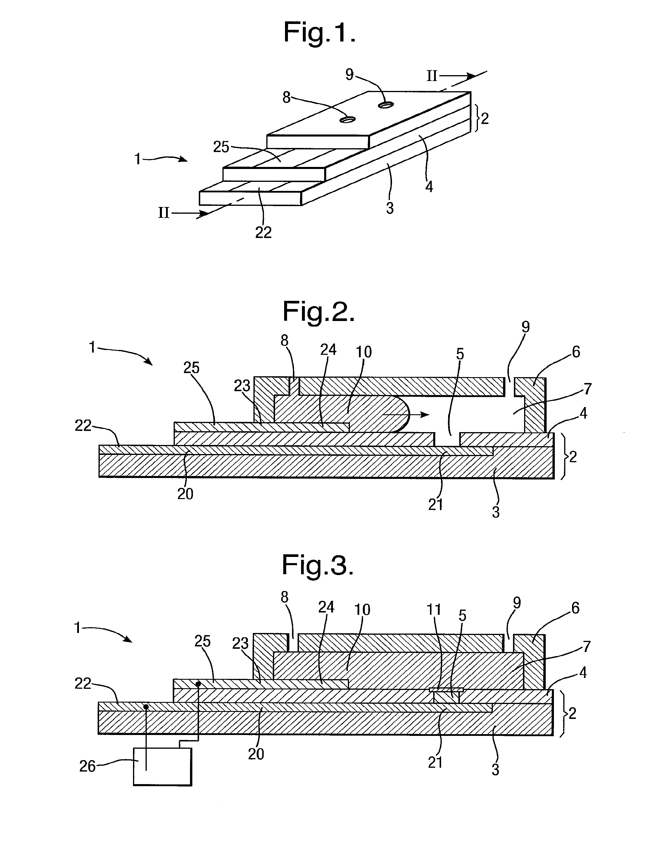
[0208]The apparatus 1 described above has been made and used experimentally to demonstrate formation of a layer 11, in particular being a lipid bilayer, and insertion of a membrane protein, for examplem α-hemolysin. The following procedure was followed after manufacture of the apparatus 1:

[0209]1) apply pre-treatment coating 30 to body 2;

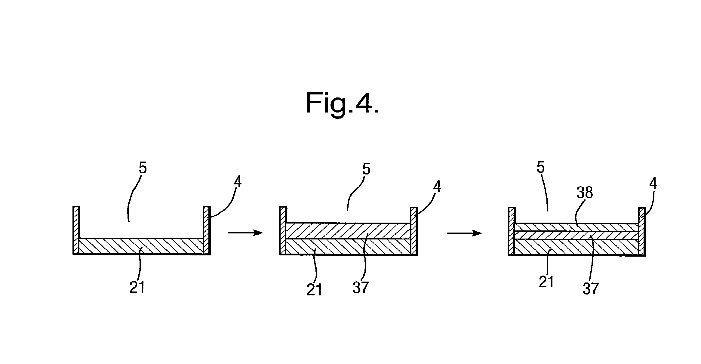
[0210]2) introduce aqueous solution 10 into chamber 7 to cover recess 5;

[0211]3) electro-wet the electrode 21;

[0212]4) remove aqueous solution 10 to un-cover recess 5 and re introduce aqueous solution 10 into chamber 7 to cover recess 5 and form the layer 11;

[0213]5) add α-hemolysin free into aqueous solution 10 and monitor insertion into layer 11.

[0214]In step 1), the pre-treatment coating 30 was hexadecane dissolved in pentane. The quantity and volume of the pre-treatment coating 30 was varied for each test to obtain the optimum conditions for formation of the layer 11. Insufficient pre-treatment coating 30 prevented formation of the layer 11 whil...

example 2

[0219]An example will now be described for a typical apparatus 1, in which the first conductive layer 20 was formed by a silver foil strips (25 μm thick, from Goodfellow) thermally laminated onto the substrate 3 using a 15 μm thick laminating film (Magicard) to form the further layer 4. A circular recess 5 of diameter 100 μm was created further layer 4 using an excimer laser, exposing a circular silver electrode 21 of diameter 100 μm. The exposed silver was chloridised electrochemically as described previously. The second conductive layer 23 was a screen printing silver / silver chloride ink printed on the top side of the body 2.

[0220]The pre-treatment coating 30, comprising 0.5 μl of 1% heaxadecane +0.6 mg / ml DPhPC in pentane, was then applied to the body 2 and dried at room temperature.

[0221]The cover 6 comprised a 1 mm thick silicon rubber body with a 250 μm thick Mylar lid. Lipid (4 μl of 10 mg / ml DPhPC in pentane) was applied to the inside of the cover 6 and allowed to dry at roo...

example 3

[0236]There will now be discussed modifications to the apparatus 1 to include plural recesses 5, commonly referred to as an array of recesses 5. The ability to easily form an array of layers 11 across an array of recesses 5 in a single apparatus 1 is a particular advantage of the present disclosure. By contrast to traditional methods of formation of lipid bilayers, the apparatus 1 has a single chamber 7, but creates the layer 11 in situ during the test and captures a reservoir of electrolyte in the recess 5 under the layer 11 which allows continuous stable measurement of current passing through protein pores inserted in the layer 11. Further the layer 11 formed is of high quality and is localised to the area of the recess 5, ideal for high-fidelity current measurements using membrane protein pores. These advantages are magnified in an apparatus 1 which forms an array of layers 11 because this allows measurements to be taken across all the layers 11 in parallel, either combining the ...


PUM

PropertyMeasurementUnit
resistanceaaaaaaaaaa
thickaaaaaaaaaa

Abstract

To form a layer separating two volumes of aqueous solution, there is used an apparatus comprising elements defining a chamber, the elements including a body of non-conductive material having formed therein at least one recess opening into the chamber, the recess containing an electrode. A pre-treatment coating of a hydrophobic fluid is applied to the body across the recess. Aqueous solution, having amphiphilic molecules added thereto, is flowed across the body to cover the recess so that aqueous solution is introduced into the recess from the chamber and a layer of the amphiphilic molecules forms across the recess separating a volume of aqueous solution introduced into the recess from the remaining volume of aqueous solution.

Description

RELATED APPLICATIONS[0001]The present application claims priority to United Kingdom Patent Application No. 0724736.4 filed on Dec. 19, 2007. The present application also claims priority to U.S. Provisional Patent Application Ser. No. 61 / 080,492 filed Jul. 14, 2008. The entire contents of the above referenced applications are incorporated herein by reference.FIELD OF THE DISCLOSURE[0002]In one aspect, the present disclosure relates to the formation of layers of amphiphilic molecules such as lipid bilayers. It is particularly concerned with the formation of high quality layers suitable for applications requiring measurement of electrical signals with a high degree of sensitivity, for example single channel recordings and stochastic sensing for biosensor or drug screening applications. In some aspects, it is concerned with applications employing arrays of layers of amphiphilic molecules, for example lipid bilayers. In another aspect, the present disclosure relates to the performance of...

Claims


Application Information

Patent Timeline
Patent Type & Authority Applications(United States)
IPC IPC(8): C12Q1/68
CPCC12Q1/6869G01N33/48721B01L2300/0645B01L2300/161B01L3/502707B01D67/00G01N27/26G01N27/403G01N33/487G01N27/3278B01L3/50273B01L2400/0421B01L2400/0427G01N27/44791G01N27/453
Inventor REID, STUART WILLIAMREID, TERENCE ALANCLARKE, JAMES ANTHONYWHITE, STEVEN PAULSANGHERA, GURDIAL SINGH
Owner OXFORD NANOPORE TECH LTD
Why Eureka
Try Eureka