
System and method for detecting number of layers of a few-layer graphene

a graphene and number detection technology, applied in the field of system for detecting the number of layers of a few-layer graphene, can solve the problems of significant time-consuming and laborious verification, the inability to determine the number of layers of an flg, and the technique based on afm also requires a significant amount of time to complete a measurement, so as to overcome the restrictions of substrate thickness and structure, easily and accurately detect the number, and effectively implement detection and analysis

Active Publication Date: 2014-12-25
NATIONAL CHUNG CHENG UNIV
View PDF4 Cites 10 Cited by
  • Summary
  • Abstract
  • Description
  • Claims
  • Application Information

AI Technical Summary

Benefits of technology

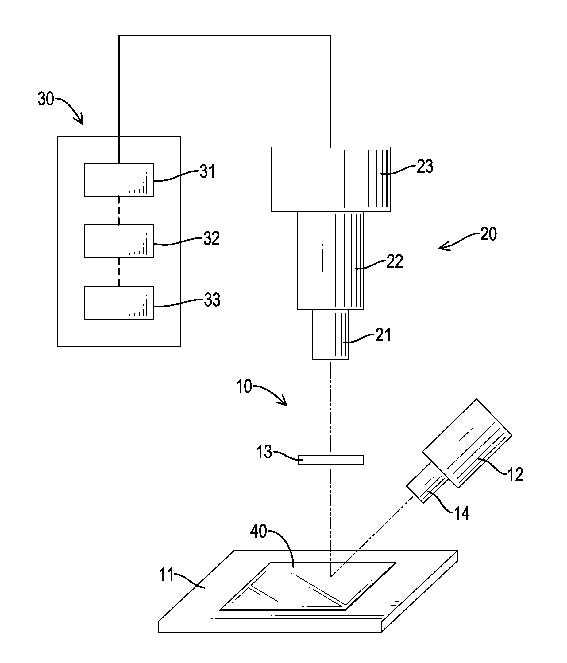
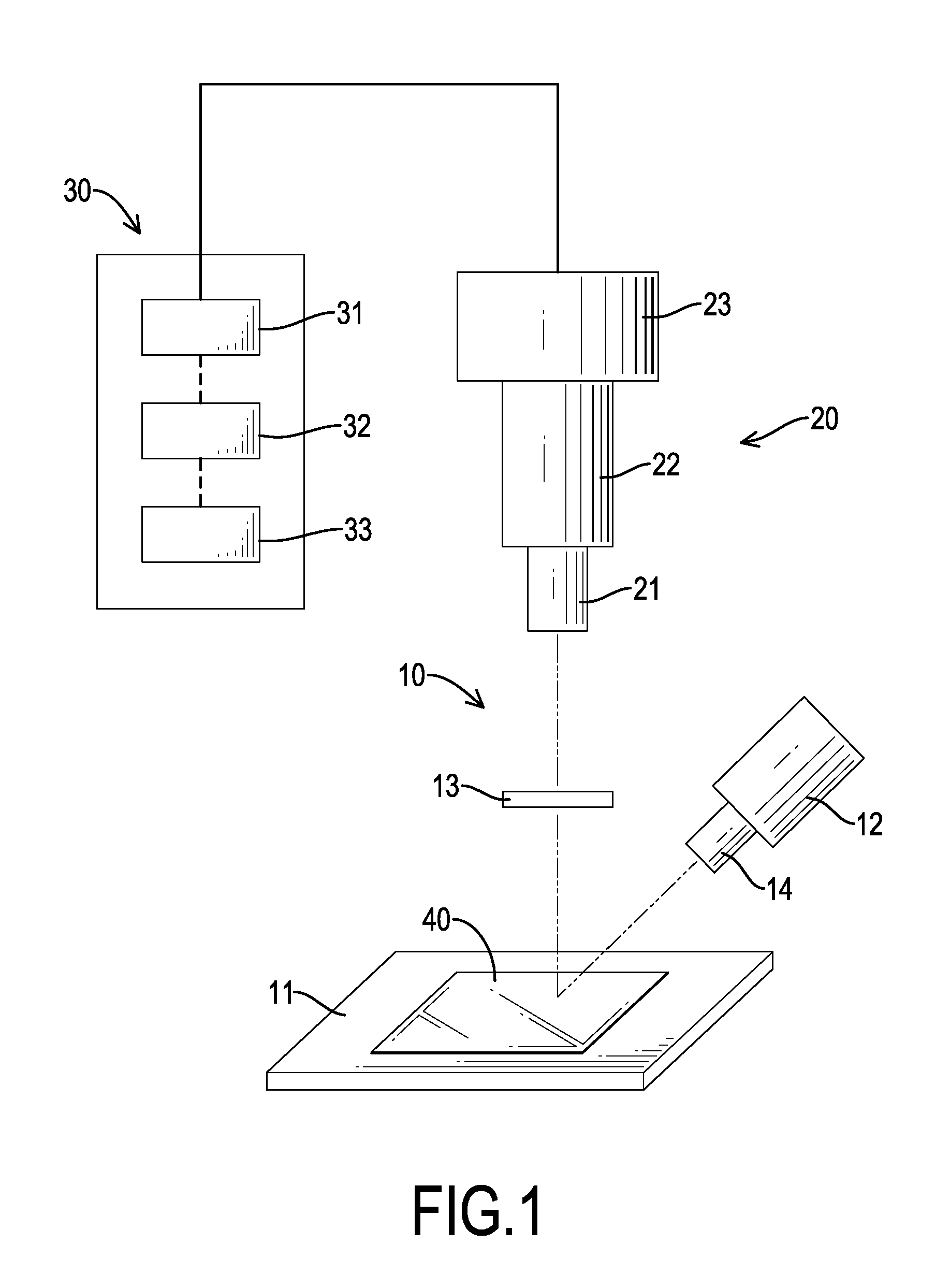
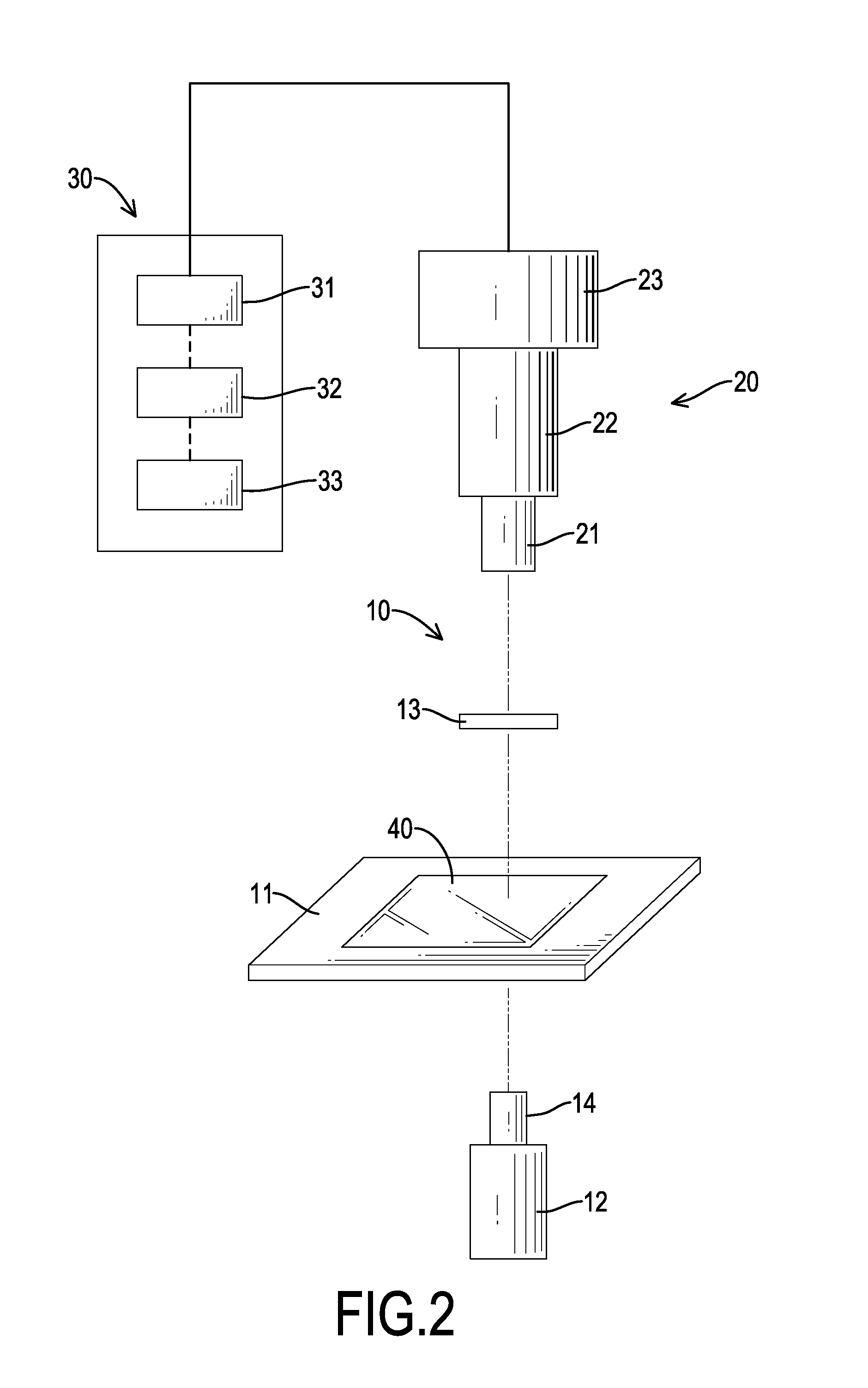
The present invention is a system and method that uses multispectral image reproduction to quickly detect the layers of FLGs (fiber-reinforced glass) on transparent or non-transparent substrates. This approach overcomes limitations of prior art methods and provides a cost-effective and efficient means to verify the number of layers of FLG products and improve quality control. The invention employs optical microscopes and CCDs to capture color information without adjusting color alternation caused by illumination. The straightforward and simple algorithms and structure of the apparatuses for the method and system invention save time and intense labor and do not require expensive instruments. Overall, this invention provides an effective and efficient technique to conveniently detect the layers of FLGs.

Problems solved by technology

Validation of the information obtained with the aforementioned techniques based on Raman spectroscopy or transmission spectroscopy, however, requires verifications that are significantly time-consuming and labor-intensive.
In addition, the technique based on Raman spectroscopy bears certain vague zones within which the number of layers of an FLG cannot be determined.
It is to be noted that such a technique based on AFM also requires a significant amount of time to complete a measurement.
The conventional technologies employing optical microscopy, however, are not applicable without substrates of specific thicknesses.
It is also to be noted that, these conventional technologies are not feasible with transparent substrates.
The conventional optical microscopic technologies fail to visualize distinguishable contrast for examining numbers of layers of FLGs.

Method used


Image

  • System and method for detecting number of layers of a few-layer graphene
  • System and method for detecting number of layers of a few-layer graphene
  • System and method for detecting number of layers of a few-layer graphene

Examples


example 1

[0088]The instant example relates to preparation of an FLG.

[0089]In the instant example, a copper foil is employed as a catalyst for developing large-area single-layer graphene thin films under a low pressure environment, using methane as a carbon source. Developed graphene thin films are then transferred with polymethylmethacrylate (PMMA) to substrates of various types, such as silica / silicon substrates or glass substrates. Details for preparing the FLG are within the scope of the prior art and thus are omitted here.

[0090]With reference to FIG. 5, a 3-layer FLG is formed on a silica / silicon substrate. On the silica / silicon substrate there are zero-layer (marked with the symbol “0L”) regions, that is, bare substrate without being covered by graphene, and one-layer (marked with the symbol “1L”), two-layer (marked with the symbol “2L”) and three-layer (marked with the symbol “3L”) regions covered respectively by corresponding layers of graphene.

[0091]With reference to FIG. 6, a 5-laye...

example 2

[0092]The instant example relates to a matrix of transformation between a spectrometer and an image-acquiring device. The image-acquiring device employed in the instant example comprises an optical microscope and a CCD camera operably connected to the microscope.

[0093]The spectrometer employed in the instant example is model number QE65000 spectrometer of Ocean Optics. The spectrometer is used to obtain transmission spectra of the 24 colors listed in Macbeth ColorChecker within the visible band of spectrum.

[0094]A model is built by multispectral calculation based on the obtained transmission spectra of the 24 colors. The color differences between simulated colors and the image-acquiring device are shown in Table 2, which lists the 24 colors used to build modules for image reproduction as well as the 24 colors' respective reflection spectra and the color differences between simulation colors and microscopic colors. In Table 2, the 24 colors are numbered and listed in reversed order o...

example 3

[0103]The instant example relates to color-reproduction using simulation spectra.

[0104]Every pixel of the image obtained by the spectrometer are multiplied by RGB to generate linear regression matrix [C], which gives corresponding XYZ values with calculation with Equations 2 to 4. The simulation spectrum of each color (380 nm to 780 nm band) is obtained via Equation 12.

[Spectra]380-780nm=[E][M][XYZ][Equation12]

[0105]With the technique of the present invention, the spectrum obtained with the spectrometer under halogen light source is divided by the spectrum obtained with the image-acquiring device under the image-acquiring illumination environment and then multiplied by a spectrum of a new substitution light source. The technique of the present invention makes possible the reproduction of colors under the substitution light source, which may be any light source.

[0106]In order to confirm the feasibility of color reproduction, the error between the actual spectrum and the simulation sp...


PUM


Abstract

Provided are a system and a method for detecting a number of layers of few-layer graphene employing multispectral image reproduction process to provide rapid detection of numbers of layers of few-layer graphenes on transparent or non-transparent substrates. The application of the system and method in relevant industries expedites validation and / or verification of the number of layers of an FLG product and improves the quality control efficiency thereof.

Description

BACKGROUND OF THE INVENTION[0001]1. Field of the Invention[0002]The present invention relates to a system for detecting the number of layers of a few-layer graphene, especially to a system with an image analysis and processing means. The present invention also relates to a method for detecting the number of layers of a few-layer graphene, especially to a method using an image analysis and processing means.[0003]2. Description of the Prior Art[0004]The visualization of graphene is regarded as an issue of increasing importance to the developing graphite technology, especially regarding confirming the number (“N”) of layers of a few-layer graphene (hereinafter “FLG”). Conventional techniques for distinguishing number of layers of FLG include: Raman spectroscopy, transmission spectroscopy, atomic force microscopy (hereinafter “AFM”) and optical microscopy.A. Raman Spectroscopy and Transmission Spectroscopy[0005]As described in reference 17, Raman spectroscopy allows detection of number ...

Claims


Application Information

Patent Timeline
Patent Type & Authority Applications(United States)
IPC IPC(8): G01J3/42H04N5/357H04N5/232G01J3/44
CPCG01J3/42H04N5/3572H04N5/23296G01J3/44G01J3/28G01N21/31H01L22/10G01N21/8422G06T7/0004H04N1/6013G01B11/0625G06T7/001H01L22/12G01B11/06G01J3/457G01B11/0633G01J2003/2826G06F18/24
Inventor WANG, HSIANG-CHENWU, GUAN-HUANGYANG, JHE-MING
Owner NATIONAL CHUNG CHENG UNIV
Learn More