

Coated cutting tool
a cutting tool and coating technology, applied in the field of coating cutting tools, can solve the problems of prior art cathodic arc deposition process, coating delamination, flaking along the edge of the coated cutting tool insert, etc., and achieve the effect of improving the wear resistance of coated cutting tools
- Summary
- Abstract
- Description
- Claims
- Application Information
AI Technical Summary
Benefits of technology
Problems solved by technology
Method used
Image

Examples
example 1
[0070]A (Ti,Al)N coating was deposited on a S1 substrate in a nitrogen atmosphere using five plate-shaped targets, each plate-shaped target comprising 40 at-% Ti and 60 at-% Al.
[0071]Prior to loading the substrate into the deposition system the substrate was subjected to dry blasting to obtain a honing to an edge radius of 30-60 μm followed by wet blasting to clean the substrate from residues from the dry blasting step. The dry blasting was performed using a nozzle with diameter 10 mm arranged at a distance of about 150 mm and an angle of about 45° relative the rake side of the substrate and 100 mesh alumina particles at a pressure of about 0.4-0.6 MPa, i.e. the particles impinging with a 45° angle on the rake side of the substrate. The wet blasting was performed using a nozzle with diameter 9.5 mm arranged at a distance of about 150 mm and an angle of about 45° relative the rake side of the substrate and 360 mesh alumina particles at a pressure of about 0.4 MPa. The duration of the...
example 2
[0076]A (Ti,Al)N coating was deposited on a S2 substrate in a nitrogen atmosphere using five plate-shaped targets, each plate-shaped target comprising 40 at-% Ti and 60 at-% Al.
[0077]Prior to deposition, the substrate was subjected to pre-treatment, horizontally arranged and plasma etched in accordance with Example 1. The coating was deposited using the following deposition conditions: temperature 450° C., nitrogen pressure 5 Pa, arc current 400 A, bias voltage 35.5 V (DC) and cathode voltage 17.5 V. After deposition the coating was subjected to post-treatment in accordance with Example 1.
[0078]The thickness of the coating was 14 μm on the flank side and 8 μm on the rake side. The hardness was 31 GPa. The internal stress after wet blasting of the coating was −1950 MPa. Areal surface roughness of the coated cutting tool was measured on the rake side using a white light interferometer (Wyko NT9100, Veeco Instruments Ltd). A Gaussian band-pass filter that rejects wavelengths above 0.08...
example 3
[0080]A (Ti,Al)N coating was deposited on a Si substrate in a nitrogen atmosphere using one plate-shaped target comprising 40 at-% Ti and 60 at Al.
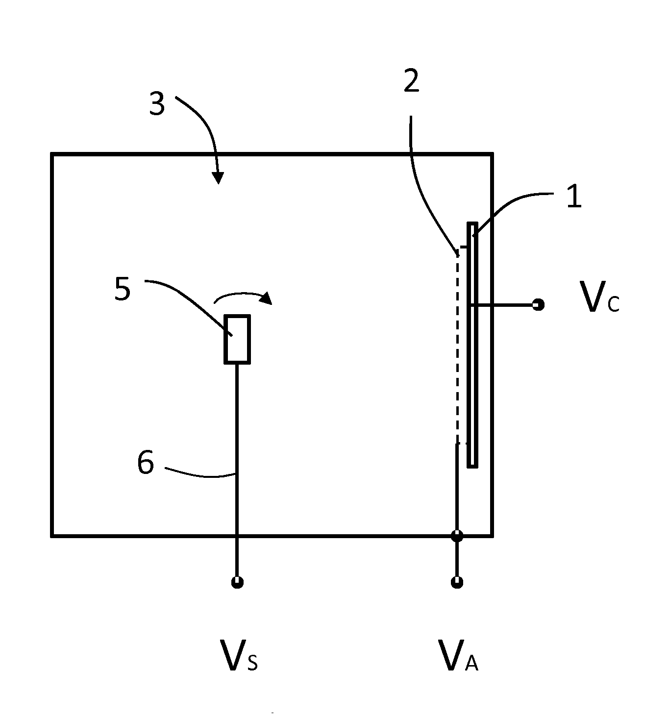
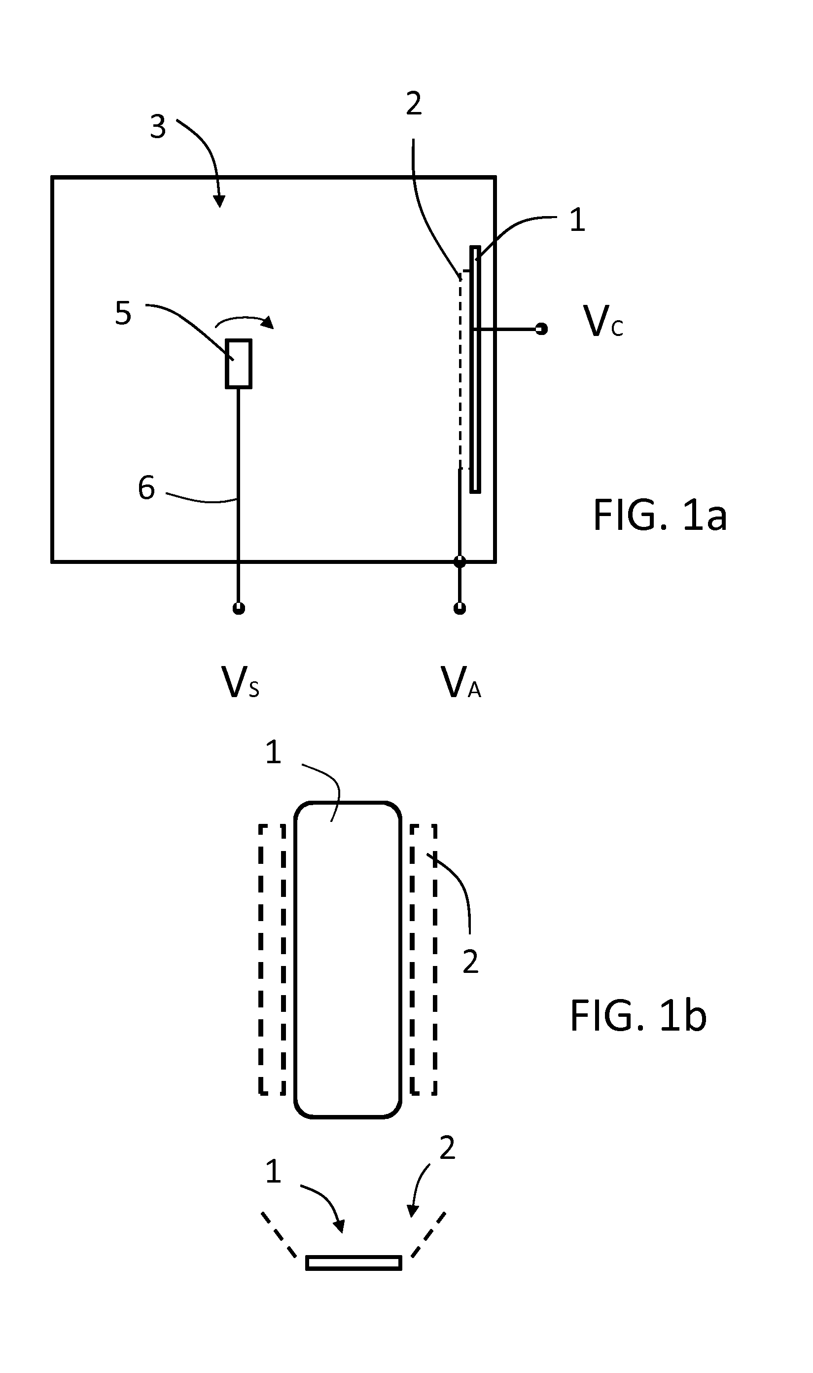
[0081]Prior to deposition, the substrate was vertically arranged, i.e. with the rake face facing the plate-shaped target, and thereafter subjected to pre-treatment and plasma etched in accordance with Example 1. The coating was deposited using the following deposition conditions: temperature 450° C., nitrogen pressure 2.5 Pa, arc current 400 A, bias voltage 19 V (DC) and cathode voltage 17.5 V. After deposition the coating was subjected to wet blasting using a nozzle with diameter 12.5 mm arranged at a distance of 50 mm and an angle of about 45° relative the rake side of the substrate and 500 mesh alumina particles at a pressure of about 0.4 MPa for about 0.5 minutes.
[0082]The thickness of the coating was 21 μm on the flank side and 24 μm on the rake side. The hardness was 27 GPa. The internal stress after wet blasting of the coating was ...
PUM
| Property | Measurement | Unit |
|---|---|---|
| Fraction | aaaaa | aaaaa |
| Fraction | aaaaa | aaaaa |
| Time | aaaaa | aaaaa |
Abstract
Description
Claims
Application Information