Light emitting diodes with quantum dot phosphors

Inactive Publication Date: 2015-01-22
PENN STATE RES FOUND
View PDF6 Cites 19 Cited by
  • Summary
  • Abstract
  • Description
  • Claims
  • Application Information

AI Technical Summary

Benefits of technology

[0010]Coupling of the quantum dot phosphors to the side walls of the etched holes is employed to achieve efficient non-radiative transfer while retaining the overlying contact electrode structures with dimensions ad

Problems solved by technology

The energy efficiency, longevity, and material usage in manufacture are all attributes that favor white LED technology, yet technical problems persist.
There are, nevertheless, a number of limits on the performance of those white LEDs due to the phosphor conversion scheme employed.
Since the existing red, yellow, and green phosphors have different chemical compositions, it is difficult to control the granule size and to mix and deposit uniform multi-phosphor films.
Also, the different aging behavior of the multiple phosphor species often makes the device performance unstable in terms of the overall wavelength output.
A more fundamental limit on the efficiency of the phosphor conversion white LEDs, however, lies in the multi-step “down conversion” scheme: high energy, blue photons produced by InGaN QW LEDs have to be absorbed by the phosphors first, and then, via impurity-level assisted transitions, are converted to low energy, long wavelength photons with a one-to-one correspondence.
This process loses a significant portion of the photon ener

Method used


Image

  • Light emitting diodes with quantum dot phosphors
  • Light emitting diodes with quantum dot phosphors
  • Light emitting diodes with quantum dot phosphors

Examples


example 1

Fabrication of Silicon Carbide Quantum Dot Phosphor LED's

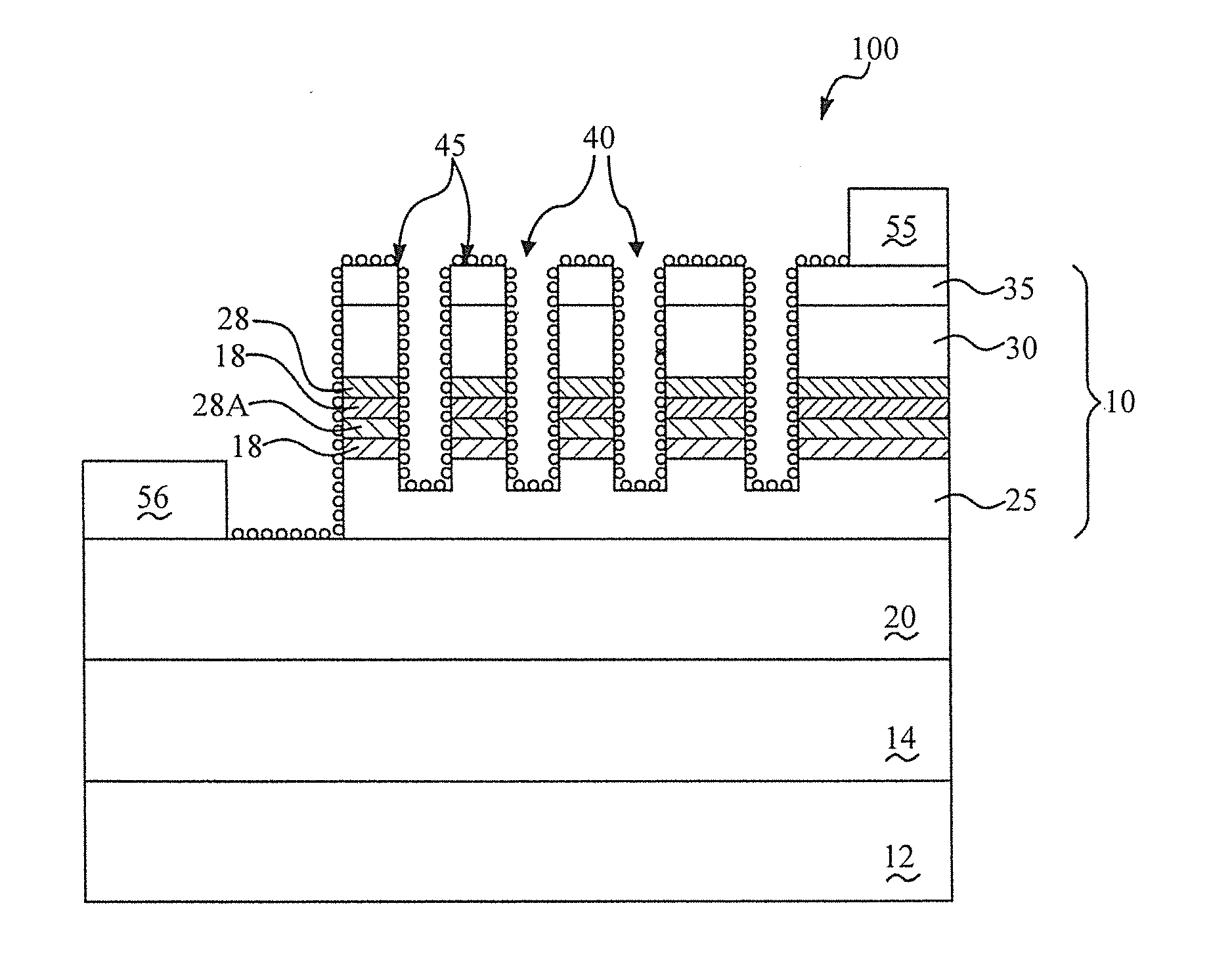
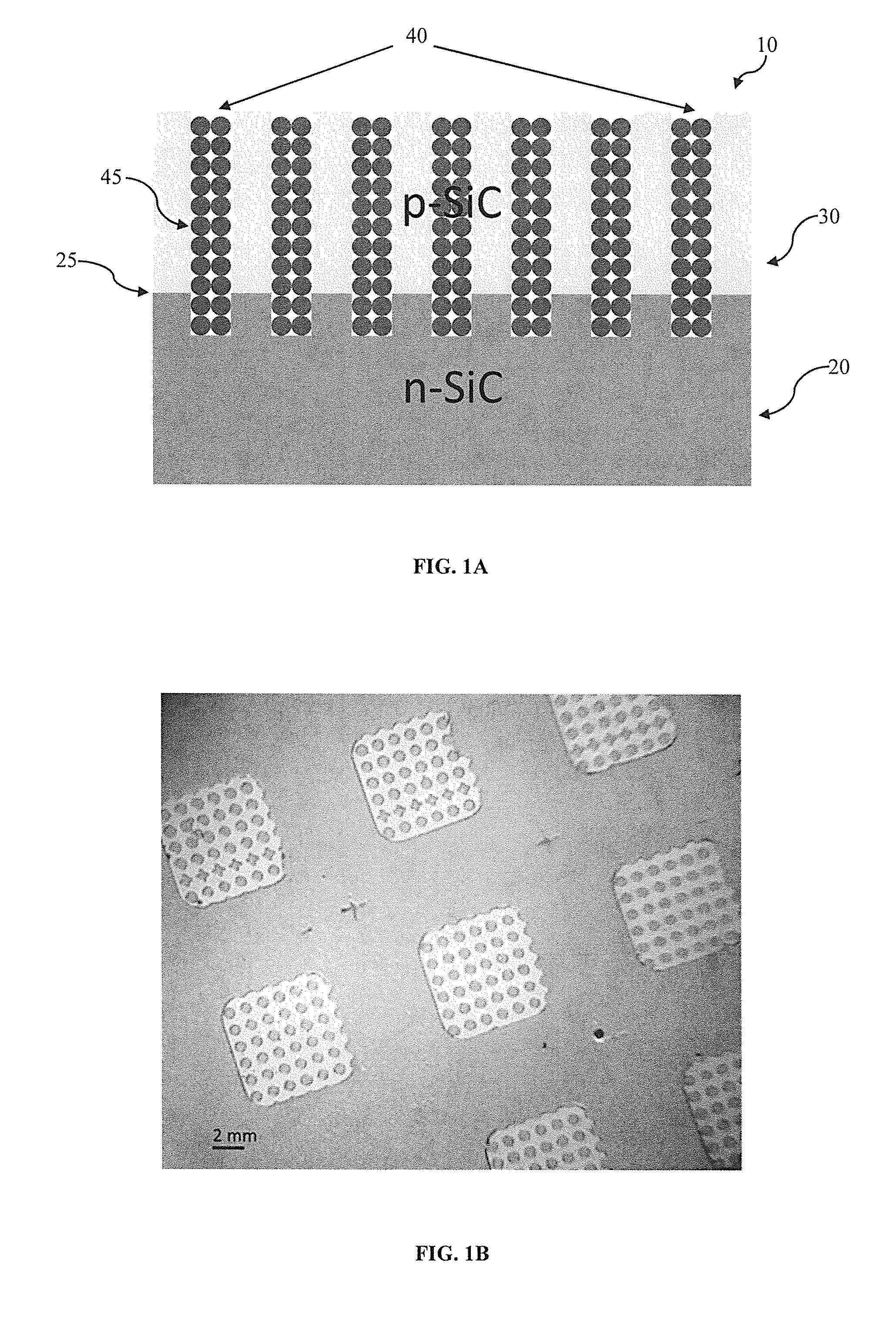
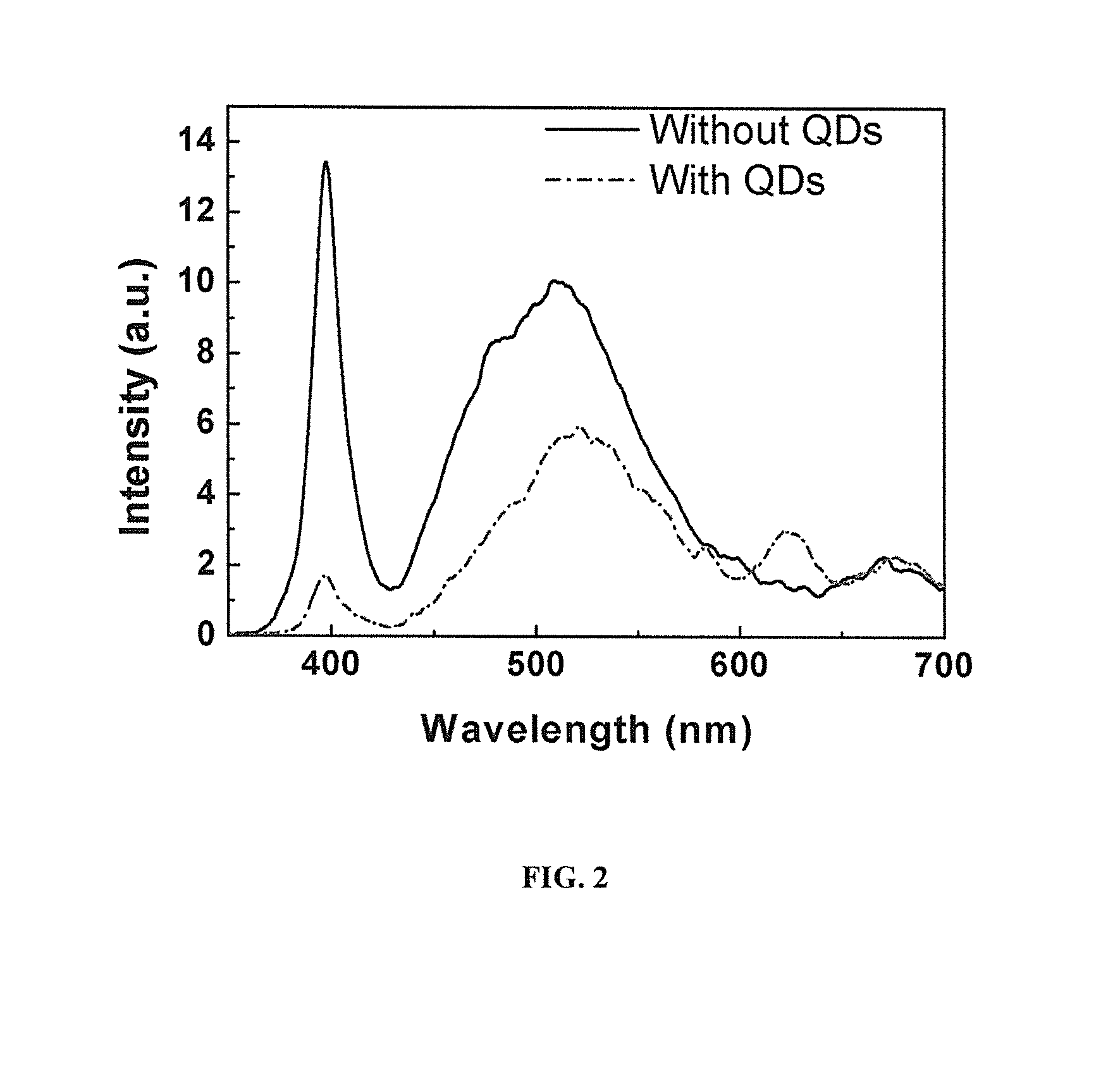
[0037]A silicon carbide (SiC) p-n junction was fabricated and surface-patterned with arrays of holes, facilitating sidewall-coupling between the QDs and the SiC p-n junction. Nonradiative energy transfer was observed from the SiC diode to colloidal QD-phosphors that accumulated in the holes. Enhanced red emission of QDs was measured from characterization of the electroluminescence spectra of the diode, with a color conversion quantum efficiency calculated to be 3.1%. Time resolved photoluminescence (TRPL) was also performed, and the photoluminescence (PL) decay lifetime of the SiC junction was found to decrease from 24.1 ns to 21.7 ns following the QD deposition, further confirming the existence of the nonradiative energy transfer path between the QDs and the SiC diode.

[0038]A SiC diode is fabricated with arrays of holes that are infiltrated with QD phosphors. The QD phosphors are colloidal CdSe / ZnS core / shell QDs (QSP-620, Oc...

example 2

Characterization of Silicon Carbide Quantum Dot Phosphor LED's

[0041]For device characterization, electrical pumping is implemented by forward-biasing the SiC p-n junction with a Keithley 2612B semiconductor parameter analyzer. The electroluminescent emission of the diode is characterized with an integrating sphere-measurement for full collection of the non-Lambertian radiation pattern. The diode is placed inside the integrating sphere (Thorlabs MA189), where the output emission of the diode is diffusely reflected by the barium sulfate-coated inner surface of the sphere and redistributed isotropically into all solid angles; the spectral and intensity detection of the light exiting from a small aperture at the sphere surface facilitates an accurate determination of the total number of photons from the nano-structured emitter. The output of the integrating sphere is coupled, via an optical fiber, to a spectrometer (Spectropro, ˜0.1 nm spectral-resolution) equipped with a p-i-n photodet...


PUM


Abstract

A quantum well-based p-i-n light emitting diode is provided that includes nanopillars with an average linear dimension of between 50 nanometers and 1 micron. The nanopillars include a laminar layer of quantum wells capable of non-radiative energy transfer to quantum dot nanocrystals. Quantum dot-Quantum well coupling through the side walls of the nanopillar-configured LED structure achieves a close proximity between quantum wells and quantum dots while retaining the overlying contact electrode structures. An white LED with attractive properties relative to conventional incandescent and fluorescence lighting devices is produced.

Description

CROSS REFERENCE TO RELATED APPLICATIONS[0001]This application is a continuation-in-part claiming priority benefit of the co-pending U.S. application Ser. No. 13 / 744,526 filed 18 Jan. 2013 which claims the priority benefit of U.S. Provisional Application Ser. No. 61 / 587,884 filed 18 Jan. 2012; the contents of each are hereby incorporated by reference.FIELD OF THE INVENTION[0002]The present invention relates in general to a light emitting diode (LED) and in particular to a white light LED based on semiconductor quantum dots (QDs) used as phosphors.BACKGROUND OF THE INVENTION[0003]White light emitting diode (LED) based solid-state lighting is commanding much attention worldwide for its promise of energy savings compared to incandescent and even compact fluorescent lighting. The energy efficiency, longevity, and material usage in manufacture are all attributes that favor white LED technology, yet technical problems persist. The predominant white LED technology involves the employment of...

Claims


Application Information

Patent Timeline
IPC IPC(8): H01L33/06H01L33/34H01L33/40H01L33/00H01L33/12H01L33/50
CPCH01L33/0012H01L33/06H01L33/34H01L33/12H01L33/40H01L33/502H01L33/343B82Y10/00B82Y20/00H01L33/20
Inventor ZHANG, FANXU, JIANMOHNEY, SUZANNE
Owner PENN STATE RES FOUND
Why Eureka
Try Eureka