
Method and apparatus for non-abaltive, photoaccoustic compression machining in transparent materials using filamentation by burst ultrafast laser pulses

a technology of ultrafast laser pulses and compression machining, which is applied in the direction of manufacturing tools, welding/soldering/cutting articles, transportation and packaging, etc., can solve the problems of low throughput times of systems, inability to achieve the effect of reducing collateral damage and minimizing entrance distortion

Active Publication Date: 2015-02-05
KINESTRAL TECH
View PDF2 Cites 62 Cited by
  • Summary
  • Abstract
  • Description
  • Claims
  • Application Information

AI Technical Summary

Benefits of technology

This patent describes a new way to make small holes in transparent materials like silicon, glass, and sapphire. The technique has advantages including smoother hole sides, longer and deeper holes, non-tapered holes, and non-linear absorption. This method also minimizes damage and distortion during the process. Overall, this patent offers a novel way to produce high-quality holes in materials that was not previously possible.

Problems solved by technology

All of the prior art systems have low throughput times, do not work well with many of the new exotic substrate materials, have problems with the opacity of multiple level substrate stacks, cannot attain the close orifice spacing sought, propagate cracks in the material or leave an unacceptable surface roughness on the orifice sides and surface surrounding the point of initiation as detailed below.
Laser ablative machining is an active development area for singulation, dicing, scribing, cleaving, cutting, and facet treatment, but has disadvantages, particularly in transparent materials, such as slow processing speed, generation of cracks, contamination by ablation debris, and moderated sized kerf width.
Further, thermal transport during the laser interaction can lead to large regions of collateral thermal damage (i.e. heat affected zone).
While laser ablation processes can be dramatically improved by selecting lasers with wavelengths that are strongly absorbed by the medium (for example, deep UV excimer lasers or far-infrared CO2 laser), the above disadvantages cannot be eliminated due to the aggressive interactions inherent in this physical ablation process.
However, machining of transparent materials with pulses even as short as tens to hundreds of femtosecond is also associated with the formation of rough surfaces and microcracks in the vicinity of laser-formed orifices or trench that is especially problematic for brittle materials like Alumina glasses, doped dielectrics and optical crystals.
Further, ablation debris will contaminate the nearby sample and surrounding surfaces.
However, the method relies on stress-induced crack formation to direct the scribe and a mechanical or laser means to initiate the crack formation.
However, the propagation of ultrafast laser pulses (>5 MW peak power) in transparent optical media is complicated by the strong reshaping of the spatial and temporal profile of the laser pulse through a combined action of linear and nonlinear effects such as group-velocity dispersion (GVD), linear diffraction, self-phase modulation (SPM), self-focusing, multiphoton / tunnel ionization (MPI / TI) of electrons from the valence band to the conduction band, plasma defocusing, and self-steepening.
While this method potentially offers fast scribe speeds of 300 mm / s, there exists a finite kerf width, surface damage, facet roughness, and ablation debris as the internally formed voids reach the surface.
Although laser processing has been successful in overcoming many of the limitations associated with diamond cutting, as mentioned above, new material compositions have rendered the wafers and panels incapable of being laser scribed.

Method used


Image

  • Method and apparatus for non-abaltive, photoaccoustic compression machining in transparent materials using filamentation by burst ultrafast laser pulses
  • Method and apparatus for non-abaltive, photoaccoustic compression machining in transparent materials using filamentation by burst ultrafast laser pulses
  • Method and apparatus for non-abaltive, photoaccoustic compression machining in transparent materials using filamentation by burst ultrafast laser pulses

Examples


Embodiment Construction

[0031]There has thus been outlined, rather broadly, the more important features of the invention in order that the detailed description thereof that follows may be better understood and in order that the present contribution to the art may be better appreciated. There are, of course, additional features of the invention that will be described hereinafter and which will form the subject matter of the claims appended hereto.

[0032]Various embodiments and aspects of the disclosure will be described with reference to details discussed below. The following description and drawings are illustrative of the disclosure and are not to be construed as limiting the disclosure. Numerous specific details are described to provide a thorough understanding of various embodiments of the present disclosure. However, in certain instances, well-known or conventional details are not described in order to provide a concise discussion of embodiments of the present disclosure.

[0033]In this respect, before ex...


PUM

PropertyMeasurementUnit
burst frequencyaaaaaaaaaa
diameteraaaaaaaaaa
quasi-Rayleigh lengthaaaaaaaaaa

Abstract

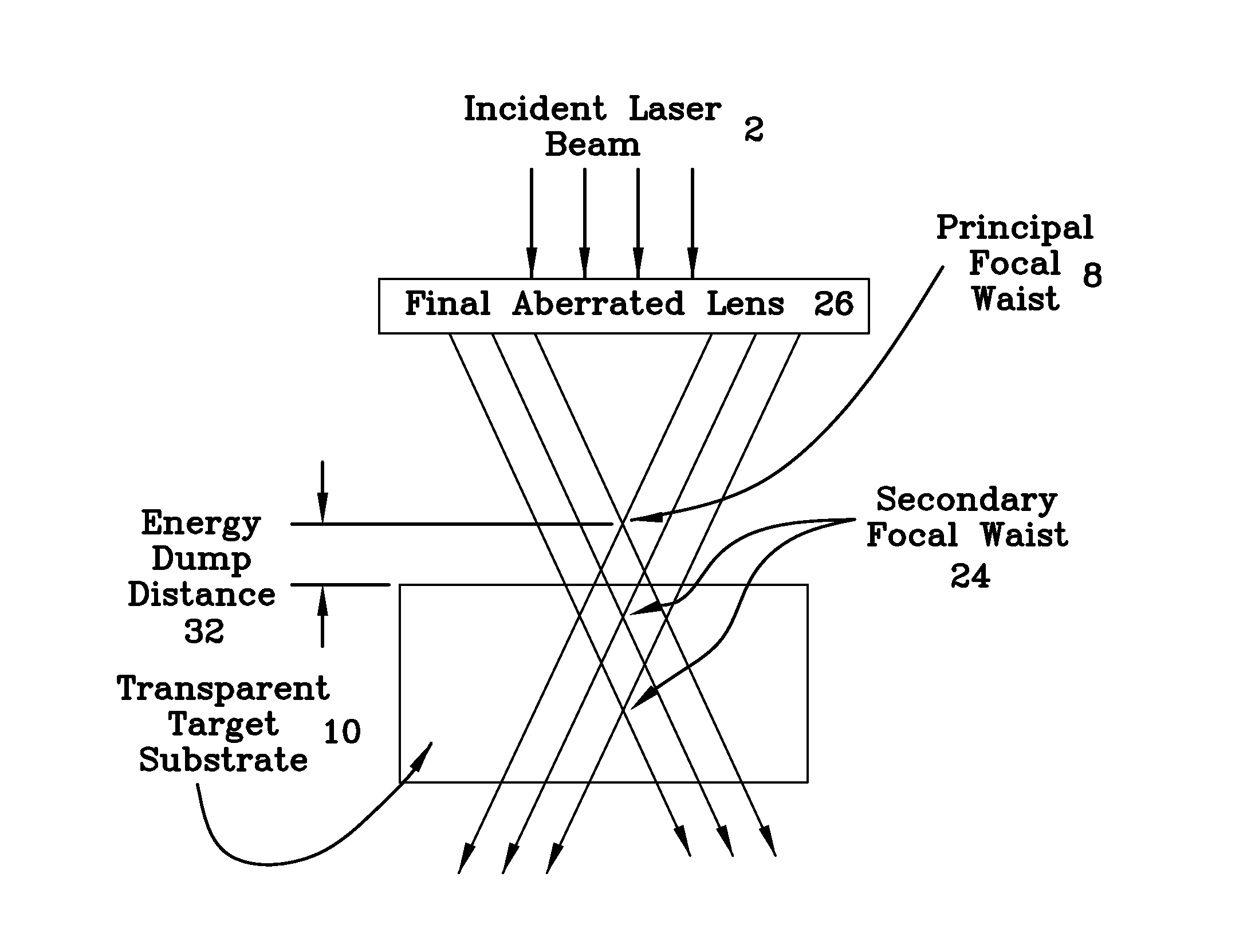
An apparatus, system and method for the processing of orifices in materials by laser filamentation that utilizes an optical configuration that focuses the incident laser light beam in a distributed manner along the longitudinal beam axis. This distributed focusing method enables the formation of filaments over distances, and the laser and focusing parameters are adjusted to determine the filament propagation and termination points so as to develop a single / double end stopped orifice, or a through orifice. Selected transparent substrates from a stacked or nested configuration may have orifices formed therein / therethrough without affecting the adjacent substrate. These distributed focusing methods support the formation filaments with lengths well beyond ten millimeters in borosilicate glass and similar brittle materials and semiconductors.

Description

BACKGROUND OF THE INVENTION[0001]The present invention relates to a non-ablative method and apparatus for drilling stopped or through orifices beginning at any depth, or in any one of a set of stacked wafers, plates or substrates, primarily, but not limited to, such transparent materials as glass, sapphire, silicon such that the structural characteristics of the orifice and surrounding material exceed that found in the prior art.[0002]There is a huge demand for drilling multiple holes in a transparent substrate such as one made of glass or a polycarbonate. One application of a drilled substrate is for use as a filter for air monitoring, particle monitoring, cytology, chemotaxis, bioassays, and the like. These commonly require orifices a few hundred nanometers to tens of micrometers in diameter that remain identical to each other and have a hole to surface area ratio that remains stable when produced in volume.[0003]Currently, the prior art material processing systems produce orifice...

Claims


Application Information

Patent Timeline
Patent Type & Authority Applications(United States)
IPC IPC(8): B23K26/00
CPCB23K26/0069B23K26/0648B23K26/18B23K26/0624B23K26/356B23K26/382B23K2103/50Y10T428/24273B23K26/40
Inventor HOSSEINI, S. ABBASNA, JUNG UNALBELO, GILBERT
Owner KINESTRAL TECH
Learn More