Magnetometer

a magnetometer and sensor technology, applied in the direction of magnetitude/direction of magnetic fields, measurement devices, instruments, etc., can solve the problems of limited sensor dimensions, limited to 50 mt, and no suitable single magnetic field sensor capable of measuring a wide range, so as to improve the signal-to-noise ratio of magnetoresistance measurements

Inactive Publication Date: 2015-04-23
INST OF GEOLOGICAL & NUCLEAR SCI
View PDF4 Cites 29 Cited by
  • Summary
  • Abstract
  • Description
  • Claims
  • Application Information

AI Technical Summary

Benefits of technology

[0034]In an embodiment, the magnetometer comprises a pair of electrodes electrically coupled to the core or a respective one of the cores for measuring magnetoresistance of the core. Preferably, the electrodes are electrically connected to a Wheatstone bridge arrangement for generating a voltage difference that is indicative of the external magnetic field. Preferably, the magnetometer comprises more than one pair of electrodes electrically coupled to the core(s) to measure the magnetic field gradient of the external magnetic field and / or to measure the magnetoresistance of the core(s) to improve the signal-to-noise ratio of the magnetoresistance measurements.

Problems solved by technology

For these and other applications, the dimensions of the sensors are limited.
However, there is no suitable single magnetic field sensor that is capable of measuring a wide range of magnetic fields (from 1 nT up to 30 T for example).
Commercial Giant Magnetoresistance (GMR) and Anisotropic Magnetoresistance (AMR) sensors are small and can measure small magnetic fields but they are limited to ˜50 mT due to saturation of the magnetic material.
SQUIDs are also small but they are expensive and they cannot be used to measure large fields.
Sensors that rely on nuclear precession are also expensive, cannot be miniaturized, and are not capable of measuring small magnetic fields.
Bulk Hall sensors are the most common magnetic sensor and can be miniaturised, but are not capable of measuring small magnetic fields.
However, the coils can only measure AC magnetic fields and the sensitivity decreases as the size is reduced.
However, they cannot measure high magnetic fields (above several 100 pT) because the magnetic core becomes saturated, the magnetization in non-linear, or the hysteresis effects become significant.
However, the technology remains limited in magnetic field range.
In particular, large field measurements are not possible due to the low field saturation, non-linearity, and hysteresis of the magnetization in the AMR material (typically >200 μT).
However, saturation of the magnetic material limits their use to fields of less than ˜0.1 T. Other magnetoresistance types, including avalanche breakdown, spin injection magnetoresistance, and geometrical magnetoresistance, have shown high sensitivity for large magnetic fields (>0.5 T).
However, no single magnetoresistance technology has been shown to provide an accurate magnetic field measurement for low to high fields.
However, and for the same reasons as mentioned above, the range of magnetic fields and hence the detected current range, is limited.

Method used


Image

  • Magnetometer
  • Magnetometer
  • Magnetometer

Examples


example 1a

Fabrication of a Pellet Core

[0199]A mixed iron oxide nanopowder was obtained using an arc discharge method. The powder contained grains with multiple nanoparticles and it was filtered to ensure that the grain size was less than 60 μm. The pellets were prepared using a hydraulic press, 3 mm die / piston assembly and a pressure of about 3 tons.

[0200]Part of the powder was analysed using a SQUID magnetometer in order to determine its magnetic properties and the results are shown in FIG. 10. The powder showed a saturation magnetization of about 72 emu / g, which is consistent with Fe2O3 and Fe3O4. The magnetization showed no hysteresis within the limit of detectability, which is consistent with the majority of the material being superparamagnetic.

[0201]Cores were made with a diameter of 3 mm and a length of 8 mm by stacking pressed pellets that were about 1 mm thick. Two electrodes were deposited on to the last pellet in a configuration similar to that shown in FIG. 5a. The gap between the ...

example 1b

Fabrication of a Thin Film Core

[0202]A core for a planar magnetometer was also fabricated by ion beam synthesis. Iron atoms were implanted in SiO2 on a Si substrate with an energy of 15 keV and a fluence of 1×10¹⁶ ions cm−2, followed by electron beam annealing at 1000° C. for two hours. A 8 mm×4 mm sample was obtained. Two electrical contacts were fabricated on the film by depositing a 2 nm thick titanium layer followed by a 20 nm thick aluminium layer using a high vacuum vapour deposition system. The dimensions of the electrodes are 4 mm×3 mm square and the gap between the electrodes was 1 mm. The titanium layer was used to improve the adhesion and electrical contact between the aluminium and the magnetic material. The samples were annealed in vacuum at 300° C. for 30 minutes to further improve the contact resistance. The magnetoresistance is plotted in FIG. 10 for a current of 0.01 mA.

example 2

Wide Dynamic-Range Measurement with a Magnetometer

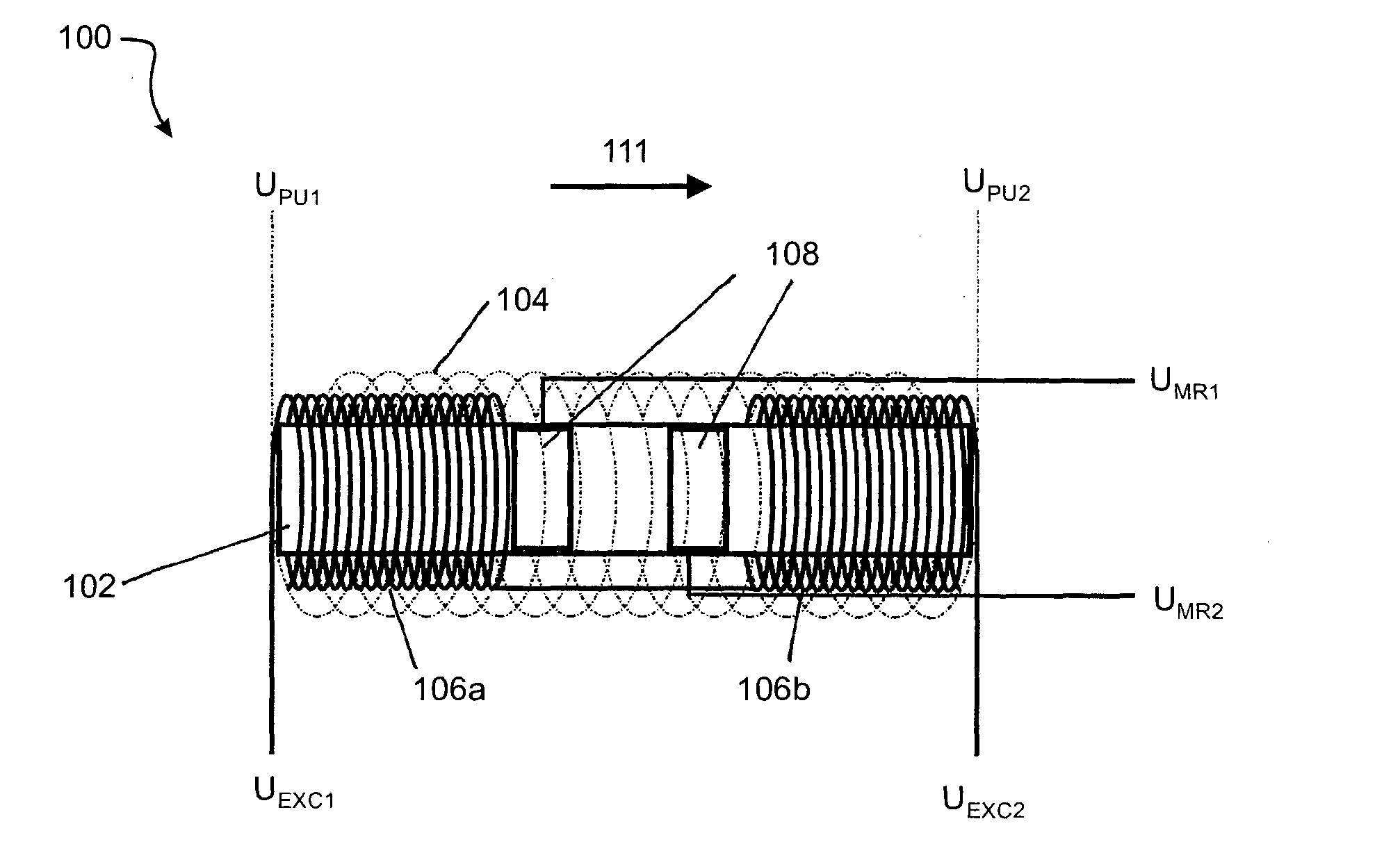
[0203]Cylindrical cores were fabricated from iron oxide nanopowder and were then pressed as described in the previous example 1a and then inserted in a hollow plastic tube with the excitation coils and pick-up coil wound around it. The excitation coils were made of 0.05 mm insulated copper wire with 275 turns each, and positioned in the same configuration as shown in FIG. 3. Thin plastic adhesive tape was used to separate the excitation and pick-up coils. The pick-up coil was wound over the excitation coils in a manner similar to that shown in FIG. 3. The wire for this coil had a diameter of 0.1 mm wire and there was 200 turns.

[0204]The excitation frequency was 40 kHz. The signal from the pick-up coil was measured using homebuilt electronics that contained a lock-in amplifier. The magnetoresistance signal was measured using a stable current source and the current was measured using a voltmeter. The system was tested in a wire-wound s...


PUM


Abstract

A magnetometer (100) for measuring an external magnetic field has at least one core (102), two excitation coils (106a), (106b), and a pick-up coil (104). The at least one core (102) has a magnetoresistance property measurable in response to the external magnetic field (111). Each excitation coil (106a), (106b) is near or around opposite ends of the core (102) or near or around a respective core. The excitation coils (106a), (106b) are configured to be driven by an alternating current to partially saturate a magnetisation of the core during part of the AC cycle. The pick-up coil (104) is near or around at least a portion of the core (102) and the excitation coils (106a), (106b). The pick-up coil (104) is configured to carry a signal induced at least in the presence of the external magnetic field (111). The induced signal is measurable in response to the external magnetic field (111).

Description

FIELD OF THE INVENTION[0001]The present invention relates generally to a magnetometer for performing wide dynamic range magnetic field measurements, and the application of such a magnetometer in, for example, magneto-electronic devices such as magnetic field sensors and current sensors.BACKGROUND[0002]Precise magnetic field measurements are necessary in a wide range of fields and applications ranging from navigation to accelerator technology and materials science. Such measurements may also be required for measuring current flowing through a conductor without contacts, for example in the case of batteries, solar cells or fuel cells. For these and other applications, the dimensions of the sensors are limited.[0003]Many different technologies have been developed based on different physical principles such as electromagnetic induction, Hall effect, Nuclear precession, Faraday rotation, Superconducting Quantum Interference Device (SQUID), magnetoresistance, giant magnetoimpedance, and f...

Claims


Application Information

Patent Timeline
Patent Type & Authority Applications(United States)
IPC IPC(8): G01R33/09
CPCG01R33/09G01R15/205G01R33/098
Inventor KENNEDY, JOHN VEDAMUTHULEVENEUR, JEROMEWILLIAMS, GRANT VICTOR MCLELLANDFUTTER, RICHARD JOHN
Owner INST OF GEOLOGICAL & NUCLEAR SCI
Why Eureka
Try Eureka