
Biomass gasifier device

a gasifier device and biomass technology, applied in the direction of combined combustion mitigation, combustible gas production, energy input, etc., can solve the problems of inability to be stable power supply, power supply shortfall, buildings and forests, etc., to reduce the troubles of the entire apparatus, improve the gasification efficiency, and operate continuously and stably for a long period.

Active Publication Date: 2015-05-21
JAPAN BLUE ENERGY
View PDF7 Cites 5 Cited by
  • Summary
  • Abstract
  • Description
  • Claims
  • Application Information

AI Technical Summary

Benefits of technology

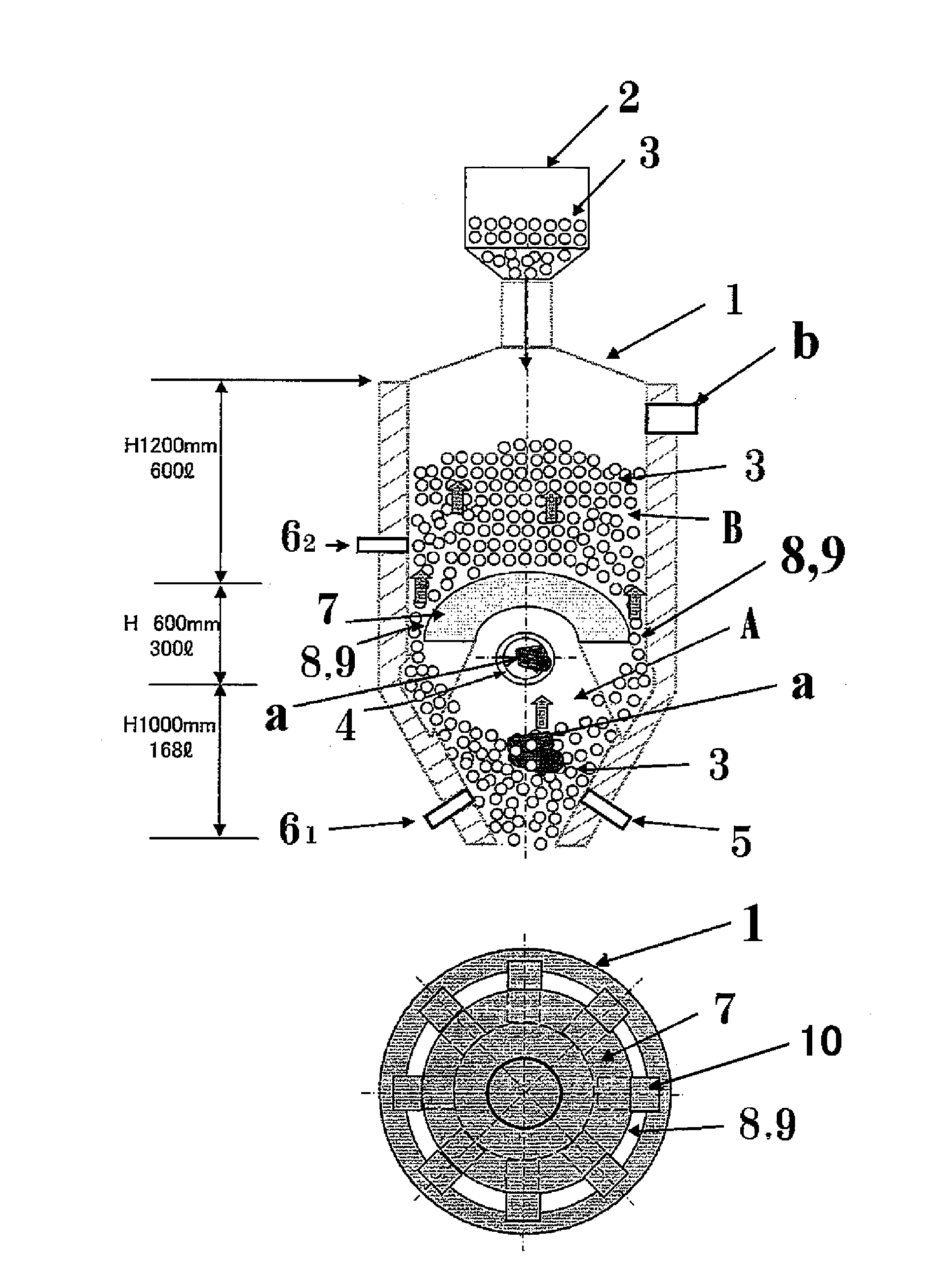
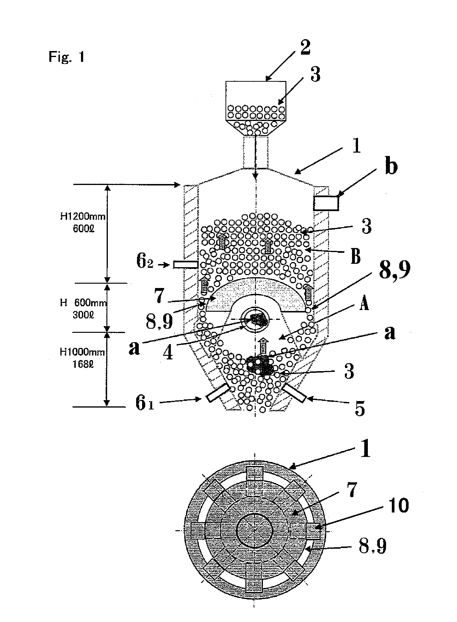
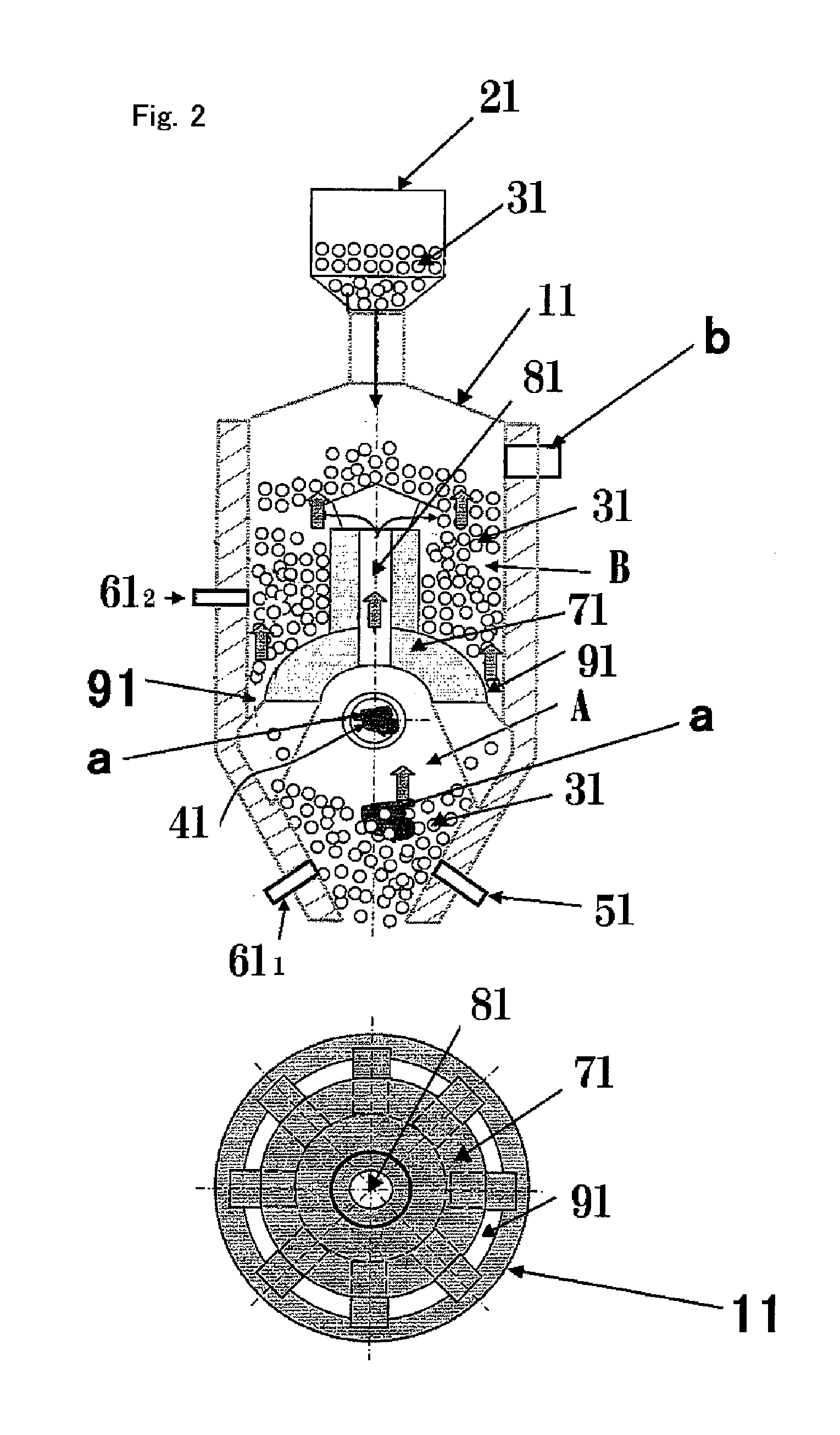
[0060]In the apparatus according to the invention, the pyrolyzed gas generated in the pyrolyzing zone does not pass through any pipe when traveling to the gas reforming zone. This configuration can avoid the clogging of the tar and dust accompanied by the pyrolyzed gas in the inner wall and valves of the pipe and the clogging of the heat carriers in the pipe. The apparatus thus can continuously and stably operate for a long period. In addition, the pyrolyzed gas ascends through the interior of the layer of heat carriers, so that the tar and dust accompanied by the pyrolyzed gas can effectively adhere to the surfaces of the heat carriers to be decomposed by the heat of the heat carriers. This configuration can improve the gasification efficiency. Furthermore, the tar and dust remaining undecomposed are discharged from the lower portion of the vessel together with the heat carriers. This configuration can reduce the troubles in the entire apparatus. In addition, the heat carriers do not pass through any pipe between the pyrolyzing zone and the gas reforming zone. This configuration can significantly reduce the loss of heat of the heat carriers, thereby improving the thermal efficiency. The configuration can also reduce the size of the entire apparatus and reduce the amounts of materials of the apparatus, leading to cost reduction.

Problems solved by technology

This situation causes a concern about a shortage of power supply, and focuses the interest on alternative renewable energy plants using photovoltaic power generation, wind power generation, geothermal power generation, hydroelectric power generation, tidal power generation, and biomass power generation, instead of nuclear power generation.
The photovoltaic power generation, wind power generation, and tidal power generation are expected to be temporary power supplies, but cannot be stable power supplies because of its unstable generation.
The collapse of buildings and forests caused by the Great East Japan Earthquake produced massive woody biomass, such as scrap wood from buildings, fallen trees in forests, timbers remaining in neglected woodlands, and thinnings.
The direct combustion power generation can process massive biomass, but the efficiency of the power generation is low.
Unfortunately, the gasification power generation needs uniform thermal decomposition of biomass and can cause troubles in an apparatus due to the tar generated by the thermal decomposition.
Unfortunately, the uniform thermal decomposition of the fed biomass is not verified.
Furthermore, the necessity of a unit for yielding the biomass having an adjusted particle size distribution leads to an increase in costs.
Unfortunately, the apparatus has a complex configuration and requires complicated manipulation.
In addition, part of the fuel gas may also be combusted and lost during the combustion of the tar.
Unfortunately, the apparatus requires increased facility and operating costs for the compressing and cooling operations.
Unfortunately, the system, which combusts the tar generated by the thermal decomposition of the biomass, cannot effectively utilize the tar.
Unfortunately, the system requires the reforming reactor in addition to the pyrolytic furnace.
Unfortunately, the system requires the preliminary carbonization of biomass and the feeding of the air for the oxidizing agent, resulting in a decrease in the gasification efficiency.
Unfortunately, neither of the method and the system using the heat carriers can sufficiently avoid troubles caused by the tar generated by the thermal decomposition.

Method used


Image

  • Biomass gasifier device
  • Biomass gasifier device
  • Biomass gasifier device

Examples


example 1

[0088]The biomass material and the reactor used for thermal decomposition of the biomass material and reformation of gas in Example 1 will now be described.

[0089]The used biomass material was scrap wood from buildings, which was coarsely crushed. The coarsely crushed scrap wood contained chopstick-sized rods, thin plates having a size of approximately a quarter of a playing card, and sawdust. The maximum dimension of the scrap wood was approximately 200 to 300 mm Table 1 shows the properties of the scrap wood.

TABLE 1CONTENTANALYTICAL VALUEMOISTURE (% BY MASS)14.3ASH (% BY MASS)0.4VOLATILE MATTER (% BY MASS)85.9FIXED CARBON (% BY MASS)13.7

[0090]The individual values in Table 1 were measured in accordance with JIS M 8812. The ash, volatile matter, and fixed carbon contents were calculated in dry basis. The moisture was measured when the biomass material had been received.

[0091]The vessel 1 illustrated in FIG. 1 was used for thermal decomposition of the biomass material and reformation...

example 2

[0094]Biomass material used in Example 2 was the same as that used in Example 1. The vessel illustrated in FIG. 5 was used for thermal decomposition of the biomass material and reformation of gas. The vessel 14 had a biomass pyrolyzing zone A and a gas reforming zone B therein and included a single cylindrical partitioning plate 74 between these zones. In the vessel 14, the gas reforming zone B had an inner diameter of approximately 800 mm, a height of approximately 1,200 mm, and an internal volume of approximately 0.6 m3. The portion of the biomass pyrolyzing zone A that surrounded the gas reforming zone B had a width of approximately 150 mm, a height of approximately 1,200 mm, and an internal volume of approximately 0.76 m3. The cone portion had a height of approximately 1,000 mm and an internal volume of approximately 0.85 m3. The entire biomass pyrolyzing zone A had an internal volume of approximately 1.61 m3. The cylindrical partitioning plate 74 had four heat carrier passages ...


PUM


Abstract

A gasification apparatus can produce hydrogen-containing gas from biomass with high thermal efficiency at low costs without severe trouble caused by tar generated by pyrolyzing the biomass, while maximizing the gasification rate of the tar. The gasification apparatus includes a biomass pyrolyzing zone for heating biomass in a non-oxidizing atmosphere, and a gas reforming zone for heating the resulting pyrolyzed gas in the presence of steam. A plurality of preheated granules and / or lumps is moved from the gas reforming zone to the biomass pyrolyzing zone, the apparatus reforms the gas generated by pyrolyzing the biomass and pyrolyzes the biomass, using the heat of the granules and / or lumps. The biomass pyrolyzing zone and the gas reforming zone is provided in a single vessel, and at least one partitioning plate is provided between the biomass pyrolyzing zone and the gas reforming zone.

Description

TECHNICAL FIELD[0001]The present invention relates to a biomass gasification apparatus, in particular, a gasification apparatus having a biomass pyrolyzing zone for pyrolyzing biomass and a gas reforming zone for mixing gas generated in the biomass pyrolyzing zone with steam and reforming the mixed gas.BACKGROUND ART[0002]Since the Great East Japan Earthquake on Mar. 11, 2011, many nuclear power plants have been shut down in terms of the safety. This situation causes a concern about a shortage of power supply, and focuses the interest on alternative renewable energy plants using photovoltaic power generation, wind power generation, geothermal power generation, hydroelectric power generation, tidal power generation, and biomass power generation, instead of nuclear power generation. The photovoltaic power generation, wind power generation, and tidal power generation are expected to be temporary power supplies, but cannot be stable power supplies because of its unstable generation. A s...

Claims


Application Information

Patent Timeline
IPC IPC(8): C10J3/84C10J3/72C10J3/56
CPCC10J3/84C10J3/56C10J3/72C10J2300/0993C10J2300/092C10J2300/1628C10J2200/154C10B49/16C10B53/02C10J3/12C10K3/006C10J2300/0906C10J2300/1853C10J2300/1807C10J2300/0976C10J2300/0916Y02E50/10Y02P20/145Y02E20/18Y02P20/133B09B3/00C10J3/00Y02P20/129
Inventor DOWAKI, NAOKIDOWAKI, KIYOSHITAKEDA, YASUIEIKEDA, HIROSHISUDA, KOUSUKEKAGAYA, FUMIEKAMIUCHI, HISASHIKAMEYAMA, MITSUO
Owner JAPAN BLUE ENERGY
Learn More