Current collector, electrode, secondary battery, and capacitor

a current collector and capacitor technology, applied in the direction of positive temperature coefficient thermistors, cell components, batteries, etc., can solve the problems of increased inner pressure, high energy density, safety problems, etc., and achieve high efficiency, high efficiency, and high efficiency.

Inactive Publication Date: 2015-10-22
FURUKAWA ELECTRIC CO LTD +2
View PDF2 Cites 35 Cited by
  • Summary
  • Abstract
  • Description
  • Claims
  • Application Information

AI Technical Summary

Benefits of technology

[0020]According to the present invention, a current collector which can realize sufficient safety function even when pressure is applied to the electrode when the cell is deformed by external force or when the electrode is in a high rate operation; an electrode, a secondary battery or a capacitor using the current collector can be manufactured with high productivity.

Problems solved by technology

Lithium ion batteries are advantageous in terms of high energy density, however, are problematic in terms of safety since they use non-aqueous electrolyte solution.
For example, the component of the non-aqueous electrolyte solution contained would decompose due to heat generation, resulting in the increase in the inner pressure.
This would cause defects such as expanded batteries.
In addition, when the lithium ion battery is overcharged, defects such as heat generation can occur.
Internal short circuit can also result in defects such as heat generation.
Accordingly, the responsiveness of the PTC element against heat generation becomes low, and is thus insufficient to prevent heat generation.
However, when the separator is located apart from the heat-generating portion, the resin may not fuse.
In addition, the heat would cause the separator to shrink, and can rather cause short circuit.

Method used


Image

  • Current collector, electrode, secondary battery, and capacitor
  • Current collector, electrode, secondary battery, and capacitor
  • Current collector, electrode, secondary battery, and capacitor

Examples


embodiment

Current Collector Having Conductive Layer Added with Inorganic Non-Conductive Material

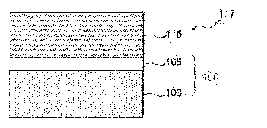
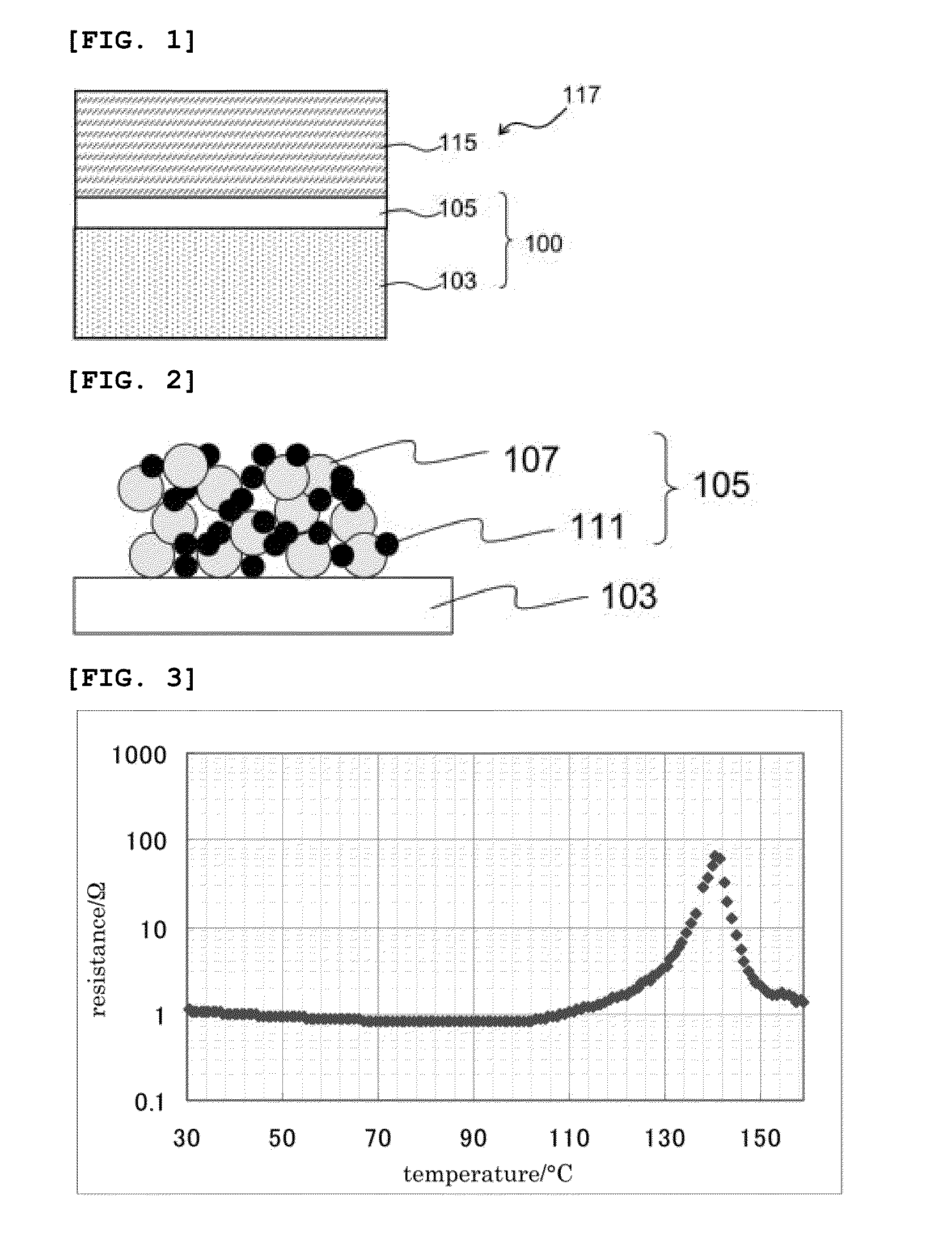
[0038]FIG. 1 is a cross-sectional view showing a structure of an electrode. In addition, FIG. 5 is a cross-sectional view showing the conductive layer of the electrode according to the present embodiment. The current collector 100 used in electrode 117 of the present embodiment comprises a metal foil 103, and a conductive layer 105 (thickness of 0.1 to 10 μm) formed on the surface of the metal foil 103. Electrode 117 of the present embodiment further comprises an active material layer 115 containing an active material, the active material layer 115 being provided on the conductive layer 105 of the current collector 100.

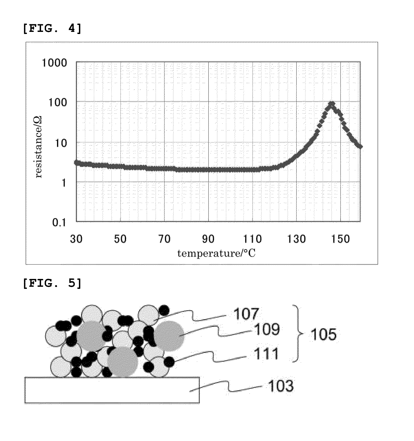
[0039]Here, as shown in FIG. 5, the conductive layer 105 comprises a conductive material 111, an inorganic non-conductive material 109, and a binder material 107.

[0040]FIGS. 6 and 7 are graphs for explaining a half width of the maximum exothermic peak observed with the binder materia...

example 1

[0091]Resin A (acid modified polypropylene emulsion, melting point of 138.6° C., solid content of 29.5%, number average particle diameter of 0.3 μm, and weight average molecular weight of 80000), acetylene black (hereinafter referred to as AB), and silica (colloidal silica, grain size of 450 nm, solid content of 40%) were mixed, followed by dispersion using disper, thereby obtaining a coating solution (resin A:AB:silica=85:10:5 by volume ratio, water medium). The coating solution thus obtained was coated onto A 1085 foil (thickness of 15 μm) so that the coating thickness would be 2 μm. The coating was then dried at 100° C. for 1 minute or 140° C. for 1 minute. Accordingly, a CC foil having a thickness of 2.2 μm was obtained. Here, the coatability of the emulsion of resin A with respect to the A 1085 foil was superior (no unevenness was found by visual observation with naked eye).

example 2

[0092]Resin A, AB, and silica (colloidal silica, grain size of 450 nm, solid content of 40%) were mixed, followed by dispersion using disper, thereby obtaining a coating solution (resin A:AB:silica=80:10:10 by volume ratio, water medium). The coating solution thus obtained was coated onto A 1085 foil (thickness of 15 μm) so that the coating thickness would be 2 μm. The coating was then dried at 100° C. for 1 minute or 140° C. for 1 minute. Accordingly, a CC foil having a thickness of 2.2 μm was obtained. Here, the coatability of the emulsion of resin A with respect to the A 1085 foil was superior (no unevenness was found by visual observation with naked eye).


PUM

PropertyMeasurementUnit
diameteraaaaaaaaaa
temperatureaaaaaaaaaa

Abstract

A current collector which can realize sufficient safety function even when the cell is deformed by external force or when the internal pressure is increased; and an electrode, a secondary battery, and a capacitor using the current collector; are provided. A current collector, including: a metal foil; and a conductive layer formed on a surface of the metal foil; is provided. Here, regarding the current collector, a temperature-resistance curve of the current collector obtained by sandwiching the current collector in between brass electrodes of 1 cm diameter, the measurement of resistance being performed with conditions of 15N of load between the electrodes and temperature being raised from ambient temperature at a rate of 10° C./min satisfies a relation of R(Ta+5)/R(Ta−5)≧1, R(Ta+5) being resistance at temperature Ta+5° C. and R(Ta−5) being resistance at temperature Ta−5° C., Ta being a temperature higher than a temperature satisfying a relation of (R(T)/R(T−5))>2.0 and first satisfying a relation of (R(T)/R(T−5))<2.0.

Description

TECHNICAL FIELD[0001]The present invention relates to current collectors, electrodes, secondary batteries, and capacitors.BACKGROUND[0002]Application of lithium ion batteries has been expanding in the fields of electronic equipments such as mobile phones and lap-top computers, owing to the high energy density. Lithium ion batteries use lithium cobalt oxide, lithium manganese oxide, lithium iron phosphate and the like as the positive electrode active material; and use graphite and the like as the negative electrode active material. Lithium ion batteries are generally structured with an electrode comprising these active materials, a porous sheet as a separator, and an electrolyte solution obtained by dissolving a lithium salt. Such lithium ion batteries have high battery capacity and battery output, excellent charge / discharge characteristics, and relatively long durability.[0003]Lithium ion batteries are advantageous in terms of high energy density, however, are problematic in terms o...

Claims


Application Information

Patent Timeline
Patent Type & Authority Applications(United States)
IPC IPC(8): H01M4/66H01G11/24H01G11/70H01M10/052
CPCH01M4/667H01M4/661H01G11/70H01G11/24H01M10/052H01G11/68H01M4/668H01C7/02H01M4/622H01M4/663H01M4/664H01M2200/106Y02E60/10Y02E60/13
Inventor IIDA, TAKAHIROMORISHIMA, YASUMASAITO, TAKAYORIHARA, HIDEKAZUKATAOKA, TSUGIOYAMABE, SATOSHIINOUE, MITSUYAKATO, OSAMUSAITO, SOHEIHONKAWA, YUKIOUYAEGASHI, TATSUHIRO
Owner FURUKAWA ELECTRIC CO LTD
Why Eureka
Try Eureka