Carbon dopant gas and co-flow for implant beam and source life performance improvement

a technology of carbon ion implantation and co-flow, which is applied in the field of carbon source materials for carbon ion implantation, can solve the problems of reducing the performance reducing the operation efficiency of the implanter tool, and requiring frequent maintenance, so as to improve the operation character of the ion implanter

Active Publication Date: 2016-01-21
ENTEGRIS INC
View PDF5 Cites 26 Cited by
  • Summary
  • Abstract
  • Description
  • Claims
  • Application Information

AI Technical Summary

Benefits of technology

[0024]The use of carbon dopant source material co-flowed to the ion implanter with at least one co-flow gas or is flowed to the ion implanter in mixture with at least one additional gas, in accordance with the present disclosure, can be employed to enhance opera

Problems solved by technology

The use of carbon monoxide or carbon dioxide gases can result in oxidation of the metal surfaces within the plasma source (arc chamber) of the ion implanter tool, and can also result in carbon residues depositing on electrical insulators.
These phenomena reduce the performance of the implanter tool, thereby resulting in the need to perform frequent maintenance.
Oxidation can result in inefficiencies in the implantation process.
In reality, feedstock gas ionization and fragmentation can results in such undesirable effects as arc chamber components etching or sputtering, deposition on arc chamber surfaces, redistribution of arc chamber wall material,

Method used


Image

  • Carbon dopant gas and co-flow for implant beam and source life performance improvement
  • Carbon dopant gas and co-flow for implant beam and source life performance improvement
  • Carbon dopant gas and co-flow for implant beam and source life performance improvement

Examples


example

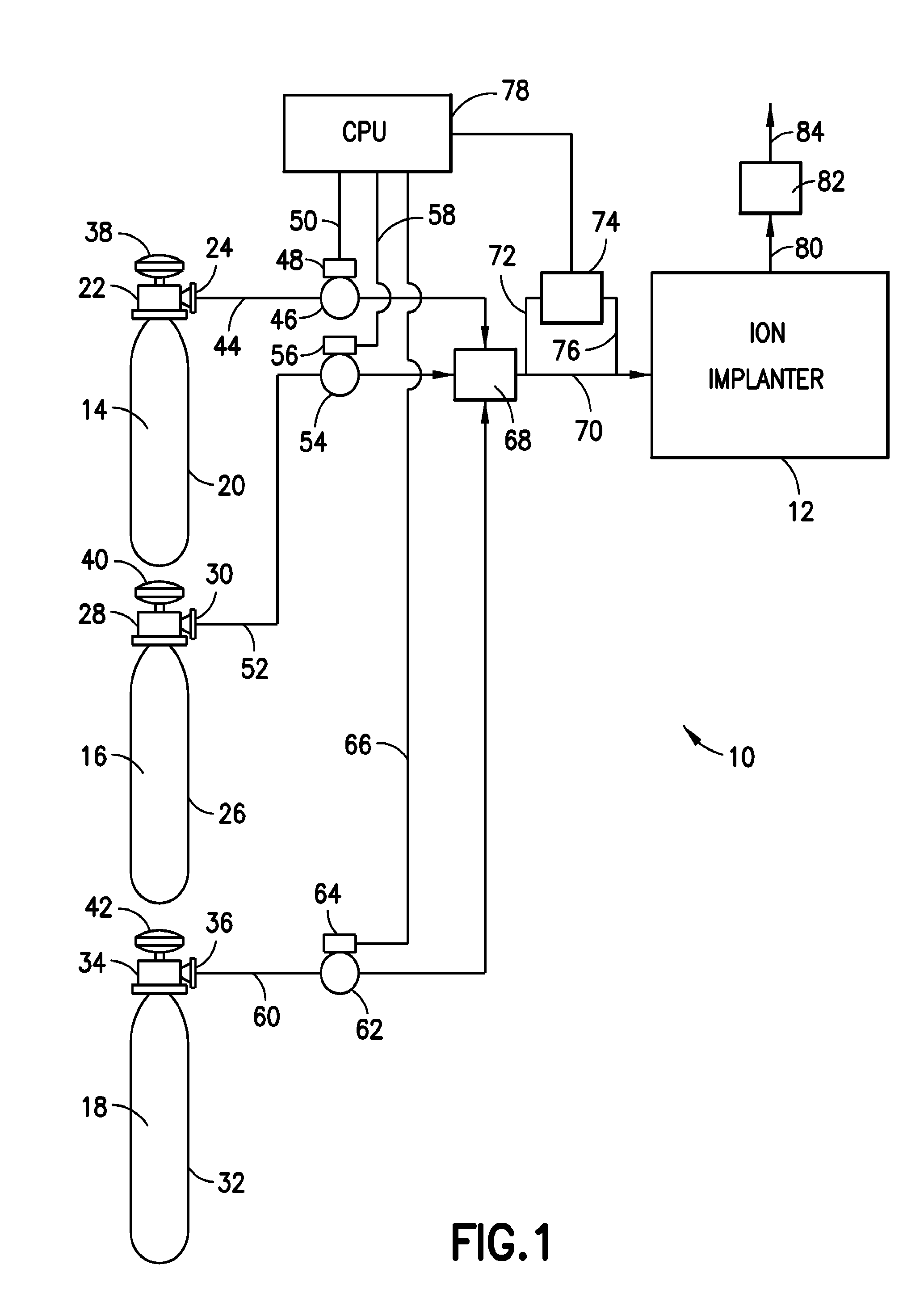
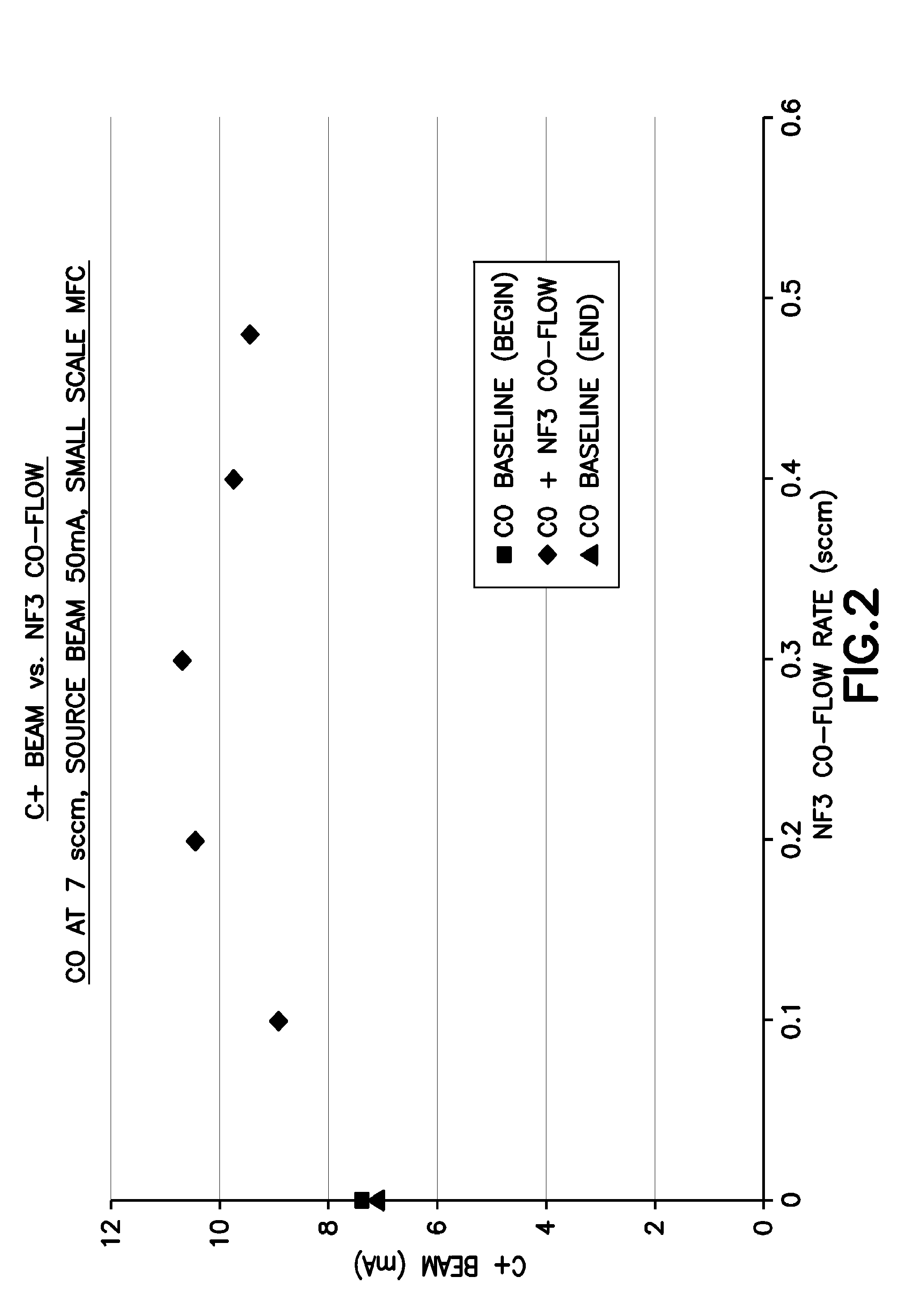
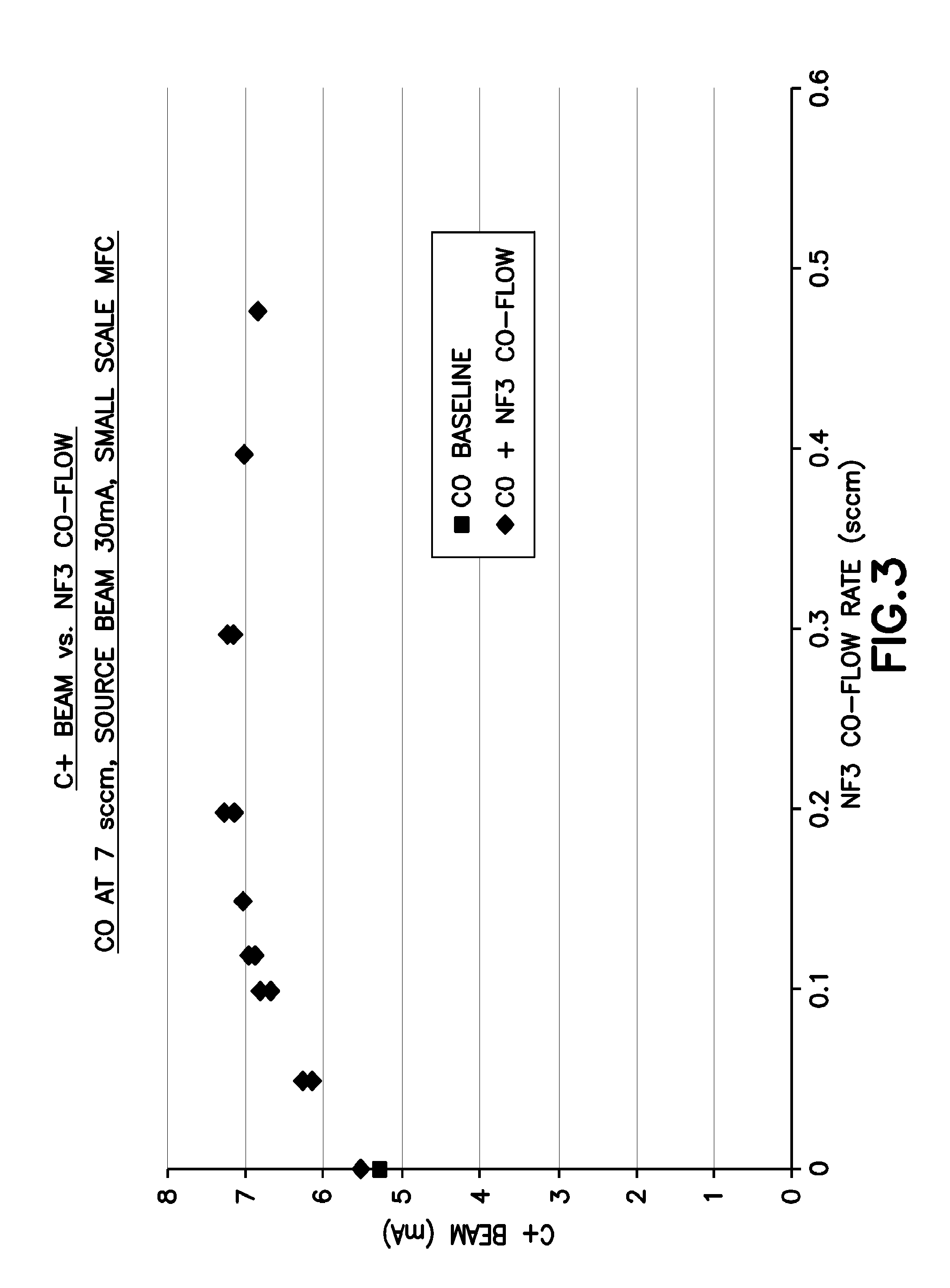
[0113]Tests were conducted utilizing an ion implant source test stand with an IHC source. In these tests, carbon monoxide (CO) was used as the carbon dopant source gas, and nitrogen trifluoride (NF3) and xenon difluoride (XeF2) were separately employed in respective test runs as the fluoro species co-flowed with the CO to the ionization chamber.

[0114]In the tests utilizing NF3 as the fluoro species, the ion implant carbon ion (C+) beam current was determined at an arc voltage (ArcV) of 110V, and source beam current of 50 mA and 30 mA in the respective runs. The CO flow rate was maintained at 7 sccm. The NF3 co-flow flow rate was varied from 0 to 0.48 sccm. The tests showed that maximum beam current was achieved at an NF3 co-flow rate in a range of from 0.2 sccm to 0.3 sccm, corresponding to about 3 vol. % to 4 vol. % NF3, based on total flow of NF3 and CO. The test results are shown in FIGS. 2 and 3, in each of which the carbon dopant species beam current (C+ Beam, in milliamps) is ...


PUM


Abstract

Ion implantation processes and systems are described, in which carbon dopant source materials are utilized to effect carbon doping. Various gas mixtures are described, including a carbon dopant source material, as well as co-flow combinations of gases for such carbon doping. Provision of in situ cleaning agents in the carbon dopant source material is described, as well as specific combinations of carbon dopant source gases, hydride gases, fluoride gases, noble gases, oxide gases and other gases.

Description

CROSS-REFERENCE TO RELATED APPLICATIONS[0001]The benefit of priority of U.S. Provisional Patent Application No. 61 / 598,817 filed Feb. 14, 2012 and U.S. Provisional Patent Application No. 61 / 625,571 filed Apr. 17, 2012 is hereby claimed under the provisions of 35 USC 119. The disclosures of U.S. Provisional Patent Application No. 61 / 598,817 and U.S. Provisional Patent Application No. 61 / 625,571 are hereby incorporated by reference herein, in their respective entireties.FIELD[0002]The present disclosure relates to ion implantation methods and systems, and more particularly, to carbon source materials for carbon ion implantation in such methods and systems.DESCRIPTION OF THE RELATED ART[0003]Ion implantation is used in integrated circuit fabrication to accurately introduce controlled amounts of dopant impurities into semiconductor wafers and is one of the processes of microelectronic / semiconductor manufacturing. In such implantation systems, an ion source ionizes a desired dopant eleme...

Claims


Application Information

Patent Timeline
IPC IPC(8): H01L21/265H01J37/317H01L31/18H01L33/00
CPCH01L21/265H01J37/3171H01L33/005H01L31/18H01J37/317H01J37/08H01J2237/022
Inventor BYL, OLEGSTURM, EDWARD A.TANG, YINGYEDAVE, SHARAD N.SWEENEY, JOSEPH D.SERGI, STEVEN G.CHAMBERS, BARRY LEWIS
Owner ENTEGRIS INC
Why Eureka
Try Eureka